Wayne-Dalton 8300 Скачать руководство пользователя страница 10

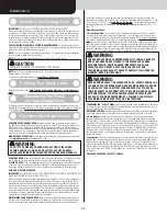
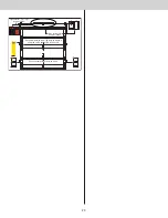
Strutting Schedule For Model 8500 Steel (White, Almond & Taupe Colored Doors)

Door 

Heights

Section 

Quantity

Door 

Configu-

rations

Door Width

10’0”

12’0” - 

14’0”

15’0” - 

16’0”

17’0” - 

18’0”

20’0”

12’0” - 

14’0”

7 - 9

Solid

N/A

2S, TS

2S, TS / 

2S, I3 / 
2S, I1 / 

2S, BS

3S, TS / 

2S, I4 / 
2S, I3 / 
2S, I1 / 

2S, BS

N/A

Top (Win-

dows)

2S, TS

2S, TS / 
2S, IW / 

2S, I1 / 

2S, BS

3S, TS / 
2S, IW / 

2S, I3 / 
2S, I1 / 

2S, BS

Inter-

mediate 

(Win-

dows)

N/A

2S, TS / 

2S, IW

Strutting Schedule For Model 8500 Steel (Brown, Black and Woodgrain Colored Doors)

Door 

Heights

Section 

Quantity

Door 

Configu-

rations

Door Widths

10’0”

12’0” - 

16’0”

17’0” - 

18’0”

20’0”

< = 8’0”

4

Solid / Top 
(Windows)

2S, TS

2S, TS / 
2S, LS / 

2S, BS

3S, TS / 
3S, LS / 

3S, BS

3S, ES

Inter-

mediate 

(Windows)

2S, TS / 
2S, IW / 

2S, BS

3S, TS / 
3S, IW / 

3S, BS

5

Solid

2S, TS

2S, TS / 
2S, LS / 

2S, BS

3S, TS / 
3S, LS / 

3S, BS

3S, ES

Top (Win-

dows)

Inter-

mediate 

(Windows)

2S, TS / 
2S, IW / 

2S, BS

3S, TS / 
3S, IW / 

3S, BS

> 8’0”

5

Solid / Top 
(Windows)

2S, TS

2S, TS / 2S, 

I2 / 2S, I1 / 

2S, BS

3S, TS / 3S, 

I2 / 3S, I1 / 

3S, BS

N/A

Inter-

mediate 

(Windows)

2S, TS / 2S, 

IW / 2S, I1 

/ 2S, BS

3S, TS / 3S, 

IW / 3S, I1 

/ 3S, BS

6

Solid / Top 
(Windows)

2S, TS

2S, TS / 2S, 

I2 / 2S, I1 / 

2S, BS

3S, TS / 3S, 

I2 / 3S, I1 / 

3S, BS

N/A

Inter-

mediate 

(Windows)

2S, TS / 

2S, IW

2S, TS / 2S, 

IW / 2S, I1 

/ 2S, BS

3S, TS / 3S, 

IW / 3S, I1 

/ 3S, BS

12’0” - 

14’0”

7 - 9

Solid / Top 
(Windows)

2S, TS

2S, TS / 2S, 

I4 / 2S, I2 

/ 2S, I1 / 

2S, BS

3S, TS / 3S, 

I4 / 3S, I2 

/ 3S, I1 / 

3S, BS

N/A

Inter-

mediate 

(Windows)

2S, TS / 

2S, IW

2S, TS / 2S, 

IW / 2S, I2 

/ 2S, I1 / 

2S, BS

3S, TS / 3S, 

IW / 3S, I2 

/ 3S, I1 / 

3S, BS

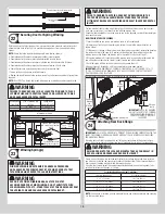
INSTALLATION ON TOP SECTION:

 Using sawhorses, lay the top section on a flat smooth 

surface. Locate and center the strut onto the section surface and up against the top edge of 

the top section. Center the strut side to side on the section. Secure strut to top section using 

1/4” - 20 x 7/8” self drilling screws at each end and at each dimple location(s), as shown.

End stile

End stile

Top  section

Dimples

1/4”-20 x 7/8” 

Self drilling 

screws

Stru

t

1/4”-20 x 7/8” 

Self drilling screws

Stru

t

Top fixture (if 

applicable)

Dimples

Strut

End stile

End stile

Top 

section

1/4”-20 x 7/8” 

Self drilling screws

Dimples

1/4”-20 x 7/8” 

Self drilling 

screws

Stru

t

Stru

t

Top fixtures 

(if applicable)

Dimples

Strut

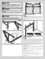
INSTALLATION ON ALL SOLID SECTIONS (EXCEPT TOP SECTION):

 Using sawhorses, lay 

the section on a flat smooth surface. Starting on the left hand side of the section, align the 

lower leafs of the appropriate graduated end hinges over the holes at the top of the end caps 

located at the top of the section. Next, align the lower hinge leafs of the #1 center hinges 

with the dimples at the center location(s) located at the top of the section. Secure the gradu-

ated end and center hinges to the section using (2) 1/4” - 20 x 11/16” self drilling screws. 

Locate and center the strut onto the section surface and up against the bottom edge of the 

hinges. Center the strut side to side on the section. Secure strut to section using 1/4” - 20 x 

7/8” self drilling screws at each end and at each dimple location(s), as shown.

1/4”-20 x 11/16” Self 

drilling screws

#1Center 

hinge(s)

#1 Graduated 

end hinge

Lower 

hinge leaf

Short stem 

track roller

End stile

End stile

Bottom section

#1Center 

hinge(s)

#1 Graduated end hinge

#1 Graduated end hinge

Lower 

hinge leaf

1/4”-20 x 11/16” Self 

drilling screws

Dimples

1/4”-20 x 7/8” 

Self drilling screws

Strut

1/4”-20 x 11/16” Self 

drilling screws

#1Center 

hinge(s)

#1 Graduated 

end hinges

Lower 

hinge leaf

Long stem 

track roller

End stile

End stile

Bottom section

#1Center 

hinge(s)

#1 Graduated end hinges

#1 Graduated end hinges

Lower 

hinge 

leafs

1/4”-20 x 11/16” 

Self drilling screws

Dimples

1/4”-20 x 7/8” 

Self drilling screws

Strut

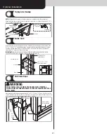
INSTALLATION ON ALL SECTION WITH WINDOWS (EXCEPT TOP SECTION):

 Using 

sawhorses, lay the section on a flat smooth surface. Starting on the left hand side of the 

section, align the lower leafs of the appropriate graduated end hinges over the holes at the 

top of the end caps located at the top of the section. Next, align the lower hinge leafs of the 

#1 center hinges / half center hinges with the dimples at the center location(s) located at 

the top of the section. Locate and center the strut onto the section surface and on top of the 

hinges. Center the strut side to side on the section. Secure strut and hinges to section using 

strut clips and 1/4” - 20 x 7/8” self drilling screws at each end hinges and at each dimple 

location(s), as shown.

NOTE:

 If your Intermediate Section has windows in it and a strut needs to be installed on that 

section, strut clips will need to be used to attach it to the section.

10

Содержание 8300

Страница 1: ...Instructions 7 Counterbalance Installation Instructions 14 Optional Installation 21 Trolley Arm Hookup 21 Inside Lock 21 Pull Down Rope 21 Maintenance 22 Cleaning Your Garage Door 22 Painting Your Ga...

Страница 2: ...STENERS IF THE ORIGINAL FASTENER WAS RED HEAD THE REPLACEMENT FASTENER MUST BE RED HEAD ALSO CONTACT WAYNE DALTON FOR FASTENER STRENGTH VALUES IF NEEDED WARNING IMPACT GUNS ARE NOT RECOMMENDED WHEN IN...

Страница 3: ...dius 187 5 4763 mm See NOTE HEADROOM REQUIREMENTS Track Type Space Needed 12 Radius 12 1 2 318 mm 14 Radius 14 1 2 368 mm Weatherstrips Level header Finished Door width Jambs Backroom Plumb jambs Fini...

Страница 4: ...g screws RED HEAD as required 5 16 x 2 Hex head lag screws as required 2 8 x 1 5 8 Self tapping screws step plate Door Section Identification Door Section Identification Of sec tions Door Type Of Sect...

Страница 5: ...hen installing your door you must use sections of the appropriate height in the right stack ing order What sections heights you need to use in what order depends on the height of your door Unless your...

Страница 6: ...eft Hand and Right Hand Vertical Tracks I3 Left Hand and Right Hand Angle Mount Vertical Track Assemblies J TORSION SPRING ASSEMBLY AS REQUIRED J1 Left Hand and Right Hand Torsion Springs As Required...

Страница 7: ...attern that is centered between the bottom jamb bracket and flag angle of the 2nd hole set Hand tighten jamb bracket using 1 1 4 20 x 5 8 carriage bolt and 1 1 4 20 flange hex nut If a top jamb bracke...

Страница 8: ...ing 1 5 16 18 x 3 4 carriage bolt and 1 5 16 18 hex nut Fasten the L reinforcement bracket to section through end cap using 1 1 4 20 x 11 16 self drilling screw Repeat the same process for the other t...

Страница 9: ...ors Door Heights Section Quantity Door Configu rations Door Widths 10 0 12 0 16 0 17 0 18 0 20 0 8 0 4 Solid Top Windows 2S TS 2S TS 2S LS 2S BS 3S TS 3S LS 3S BS 3S ES Inter mediate Windows 2S TS 2S...

Страница 10: ...g sawhorses lay the section on a flat smooth surface Starting on the left hand side of the section align the lower leafs of the appropriate graduated end hinges over the holes at the top of the end ca...

Страница 11: ...ottom of the center stile as a template drill 2 7 32 dia holes through the section Using the previously drilled holes as a guide enlarge the holes from outside the door to 7 16 dia and assemble the ou...

Страница 12: ...acing Bottom section Vertical track Floor Track roller Flag angle lag screw locations 5 16 x 2 Lag screws Or FOR ANGLE MOUNT VERTICAL TRACK ASSEMBLY Loosely fasten the slots in the wall angle to the j...

Страница 13: ...below Place the bottom half inside the top half and flush against the inside surface of the top section Adjust both the top and bottom halves out as far apart as possible on the section surface Secure...

Страница 14: ...3 4 hex head bolt and 1 3 8 16 hex nut Repeat for other side Remove nail that was temporally holding the top section in position IMPORTANT FAILURE TO REMOVE NAIL BEFORE ATTEMPTING TO RAISE DOOR COULD...

Страница 15: ...ge of the spring anchor bracket with the vertical pencil line and the center of the spring anchor bracket with the horizontal pencil line this is to ensure the torsion shaft is level between the sprin...

Страница 16: ...one of the coupler halves the spring anchor bearing torsion spring with the red winding cone and the red cable drum at the left end of the torsion keyed shaft Next on the right hand side lay the other...

Страница 17: ...ket Spring anchor bracket Attaching Counterbalance Lift Cables 20 Starting on the left hand side thread the counterbalance lift cable up and around the front side of the left hand cable drum IMPORTANT...

Страница 18: ...her sockets being careful to seat it snugly and at full socket depth 5 Hold the spring with the second winding bar and remove the first 6 Repeat Steps 2 through 5 until the complete turns have been ap...

Страница 19: ...weatherstrips to the jambs avoid pushing the weath erstrips too tightly against the face of door Weather seals Nail Weather seal Jamb Weather seal installed Jamb Header Jamb Nail NOTE Door not shown f...

Страница 20: ...6 Make sure door is not rubbing on jambs IMPORTANT IF DOOR STILL DOES NOT BALANCE PROPERLY THEN CONTACT A TRAINED DOOR SYSTEM TECHNICIAN 20...

Страница 21: ...uld be spaced ap proximately 1 8 away from the section edge IMPORTANT INSIDE LOCK S MUST BE REMOVED OR MADE INOPERATIVE IN THE UN LOCKED POSITION IF AN OPERATOR IS INSTALLED ON THIS DOOR 4 1 4 20 x 11...

Страница 22: ...n operation maintenance and testing of the operator MAINTAINING YOUR GARAGE DOOR Before you begin read all warning labels affixed to the door and the installation instructions and owner s manual Perfo...

Страница 23: ...uctions DO NOT remove cover or paint over this tag Prod uct user should inspect this tag periodically for legibility and should order a replacement tag from the door manufacturer as needed Copyright 2...

Страница 24: ...ion or repair of the Product or to any Product or component which has been damaged or deteriorated due to misuse neglect accident failure to provide necessary maintenance normal wear and tear acts of...

Страница 25: ......

Страница 26: ...rvice representative They will be happy to handle any questions that you may have Thank you for your purchase PLEASE DO NOT RETURN THIS PRODUCT TO THE STORE After installation is complete leave this I...

Отзывы: