


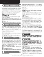

Graduated End Hinge Schedule
6 Section High Door
2”
Top
N/A
Intermediate IV
5#
Intermediate III
4#
Intermediate II
3#
Intermediate I
2#
Bottom
1#
3”
Top
N/A
Intermediate IV
7#
Intermediate III
6#
Intermediate II
5#
Intermediate I
4#
Bottom
3#
7 Section High Door
2”
Top
N/A
Intermediate V
6#
Intermediate IV
5#
Intermediate III
4#
Intermediate II
3#
Intermediate I
2#
Bottom
1#
3”
Top
N/A
Intermediate V
8#
Intermediate IV
7#
Intermediate III
6#
Intermediate II
5#
Intermediate I
4#
Bottom
3#
NOTE:
Center hinge(s) use #1 graduated end hinges at each pre-drilled vertical stile location.
The pre-drilled locations are located at the top and or bottom rails on the inside of the section
surface.
NOTE:
Some doors will receive half center hinge(s). These will be installed in between the center
hinge(s) and graduated end hinge(s).
STRuT IDENTIFICATION:
Identify your struts to determine which ones are long strut(s) or short strut(s).
Short Strut(s) are typically installed along the top rail of the top section and or along the bottom
rail of the bottom section.
Long Strut(s) are typically installed along the top and or bottom rails of sections. Measure the
height of the long strut(s) to determine if you have 2” or 3”.
NOTE:
Some struts also may or may not have holes in them. If they don’t, then prior to installing
the strut and hinge to the section surface, you may have to drill a 3/16” hole for the appropriate
fastener on one or both sides of the strut legs.
Strutting Schedule for Door Heights Less Than Or Equal to 8’0”
Product
Door Width
up To and Including
12’2”
From 12’3” To 16’0”
From 16’1” To 18’0”
Model 105
N/A
(4) 2” Struts
N/A
Model 110
N/A
(4) 2” Struts
(4) 3” Struts
Model 310/311
N/A
(4) 2” Struts
(4) 3” Struts
Strutting Schedule for Door Heights Greater Than Or Equal to 8’1”
Product
Door Width
up To and Including
12’2”
From 12’3” To 16’0”
From 16’1” To 18’0”
Model 105
(2) 2” Struts
(1) 2” Strut, per section,
Plus 1
N/A
Model 110
(2) 2” Struts
(1) 2” Strut, per section,
Plus 1
(1) 3” Strut, per section,
Plus 1
Model 310/311
(2) 2” Struts
(1) 2” Strut, per section,
Plus 1
(1) 3” Strut, per section,
Plus 1
1
1
2
Short strut
Long strut
Hinges are stamped for
identification
Center hinge(s)
(as required)
Half center hinge(s)
(as required)
Upper hinge
leaf
Lower hinge
leaf
2” Strut
3” Strut
Removing an Existing Door
IMPORTANT:
COuNTERBALANCE SPRING TENSION MuST ALWAYS BE RELEASED BEFORE ANY
ATTEMPT IS MADE TO START REMOVING AN ExISTING DOOR.
WARNING
WARNING
A POWERFuL SPRING RELEASING ITS ENERGy SuDDENLy CAN CAuSE SEvERE
OR FATAL INJuRy. TO AvOID INJuRy, HAvE A TRAINED DOOR SySTEMS TECH-
NICIAN, uSING PROPER TOOLS AND INSTRuCTIONS, RELEASE THE SPRING
TENSION.
For detailed information see supplemental instructions “Removing an Existing Door/ Preparing
the Opening”. These instructions are not supplied with the door, but are available at no charge
from Wayne-Dalton, A Division Of Overhead Door Corporation, P.O. Box 67, Mt. Hope, OH.,
44660, or at
www.Wayne-Dalton.com
.
Preparing the Opening
IMPORTANT:
IF YOu JuST REMOVED YOuR ExISTING DOOR OR YOu ARE INSTALLING A NEW
DOOR, COMPLETE ALL STEPS IN PREPARING THE OPENING.
To ensure secure mounting of track brackets, side and center brackets, or steel angles to new or
retro-fit construction, it is recommended to follow the procedures outlined in DASMA technical
data sheets #156, #161 and #164 at
www.dasma.com
.
The inside perimeter of your garage door opening should be framed with wood jamb and header
material. The jambs and header must be securely fastened to sound framing members. It is
recommended that 2” x 6” lumber be used. The jambs must be plumb and the header level.
The jambs should extend a minimum of 12” (305 mm) above the top of the opening for Torsion
counterbalance systems. For low headroom applications, the jambs should extend to the ceiling
height. Minimum side clearance required, from the opening to the wall, is 3-1/2” (89 mm), for
2” track. Minimum side clearance required, from the opening to the wall, is 4-1/2” (114 mm),
for 3” track.
IMPORTANT:
CLOSELY INSPECT JAMBS, HEADER AND MOuNTING SuRFACE. ANY WOOD
FOuND NOT TO BE SOuND, MuST BE REPLACED.
For Torsion counterbalance systems, a suitable mounting surface (2” x 6”) must be firmly at-
tached to the wall, above the header at the center of the opening.
NOTE:
Drill a 3/16” pilot hole in the mounting surface to avoid splitting the lumber. Do not attach
the mounting surface with nails.
WEATHERSTRIPS (MAy NOT BE INCLuDED):
Depending on the size of your door, you may have to cut or trim the weatherstrips (if necessary)
to properly fit into the header and jambs.
NOTE:
If nailing product at 40°F or below, pre-drilling is required.
NOTE:
Do not permanently attach weatherstrips to the header and jambs at this time.
For the header, align the weatherstrip 1/8” to 1/4” inside the header edge, and temporarily
secure it to the header with equally spaced nails. Starting at either side of the jamb, fit the
weatherstrip up tight against the temporarily attached weatherstrip in the header and 1/8”
to 1/4” inside the jamb edge. Temporarily secure the weatherstrip with equally spaced nails.
Repeat for other side. This will keep the bottom section from falling out of the opening during
installation. Equally space nails approximately 12” to 18” apart.
Backroom requirement:
Backroom is defined as the distance needed from the opening back
into the garage to allow the door to open fully.
*NOTE:
For door heights from 10’1” to 12’0”, refer to your operator manufacture installation
instructions for appropriate depth into room.
Headroom requirement:
Headroom is defined as the space needed above the top of the door
for tracks, springs, etc. to allow the door to open properly. If the door is to be motor operated,
2-1/2” (64 mm) of additional headroom is required.
BACkROOM REquIREMENTS
5
Please Do Not Return This Product To The Store. Contact your local Wayne-Dalton dealer. To find your local Wayne-Dalton dealer,
refer to your local yellow pages business listings or go to the Find a Dealer section online at www.Wayne-Dalton.com
Содержание 105/110
Страница 21: ......