Click Supervisor will be used to configure the Click 400. To install it:
1
Download the setup file from www.wavetronix.com (under
Support
).
2
Double-click on the file to run the setup wizard. Follow the steps to install.
5
Install Click Supervisor
6
Make a connection
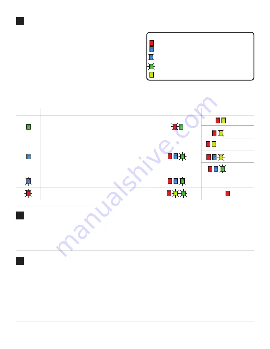
Use the device’s configuration features to make sure the Click
400 is wired and working properly. The Click 400 has four LEDs
that monitor device activity and help you select operating modes,
as well as a push-button, labeled Mode Switch, also used for oper-
ating modes.
1
Autobaud device (see table).
2
Set one of the devices as a server (by default, and after a
reset, the devices are clients) by setting it in Link Test server
mode. When the link test starts, press the push-button again;
the test will end and the device will stay a server. Your Click
400 installation will not work until you do this.
Hold the push-button to cycle through modes, then release when the desired mode is reached.
Selection Operating mode
Running
Complete
Autobaud – Release push-button when green light is
solid to autobaud to sensor. Autobauding will set the
device as a client.
failure
success
Link Test (client)– Release push-button when blue LED is
solid to start Link Test mode as a client. The link test can’t
be run until the client and server devices are set to the
same RF channel. See step 9.
can’t find server
invalid data
valid date
Link Test (server) – Release push-button when blue LED
is blinking to start Link Test mode as a server.
results will be shown on
client module
Reset – Release push-button when red LED is blinking to
reset to factory defaults.
1
Make sure there is a connection between the Click 400 and the computer that Click Supervisor is on. This can be
through the DB-9 connector on the module or through another device also on the T-bus; for example, the Click 421 can
communicate with the computer through Bluetooth.
2
Run Click Supervisor and select
Communication
. The Click 400 can only be configured using serial communication.
3
Click
Settings
to make any necessary changes to the settings, such as the port or the baud rate. Click
OK
to return to the
Communication screen, then click
Connect
. Keep the Click ID set to 0.
4
In the next screen, Click Supervisor will display all the devices it discovers. When the Click 400 appears, select it and
click
Select
. Click Supervisor will connect to the device.
4
Use on-device configuration features
LED activity-indicating functions:
Red –
Device has power
Blue –
Device is a client and can see a server
Blue flash –
Device is a server
Green flash –
Device is receiving data
Yellow –
Device is transmitting data


