background image

4-52

Using the numeric entry keys, enter the start and stop information for
the date and time as well as the interval amount. Press the 

ENTER

key after each parameter is entered to update the display. Use the 

Up

and 

Down

 arrow soft keys to select the parameter to be entered. Press

the 

OK

 soft key to commence the Schedule Auto Test. If the first

interval is to commence immediately, the unit will prompt you to
enter the ambient temperature. The temperature displayed is the
temperature sensed by the unit. Use the numeric entry keys to enter
the ambient temperature. Press the 

OK

 soft key when the desired

temperature has been entered.  If the first interval is to commence
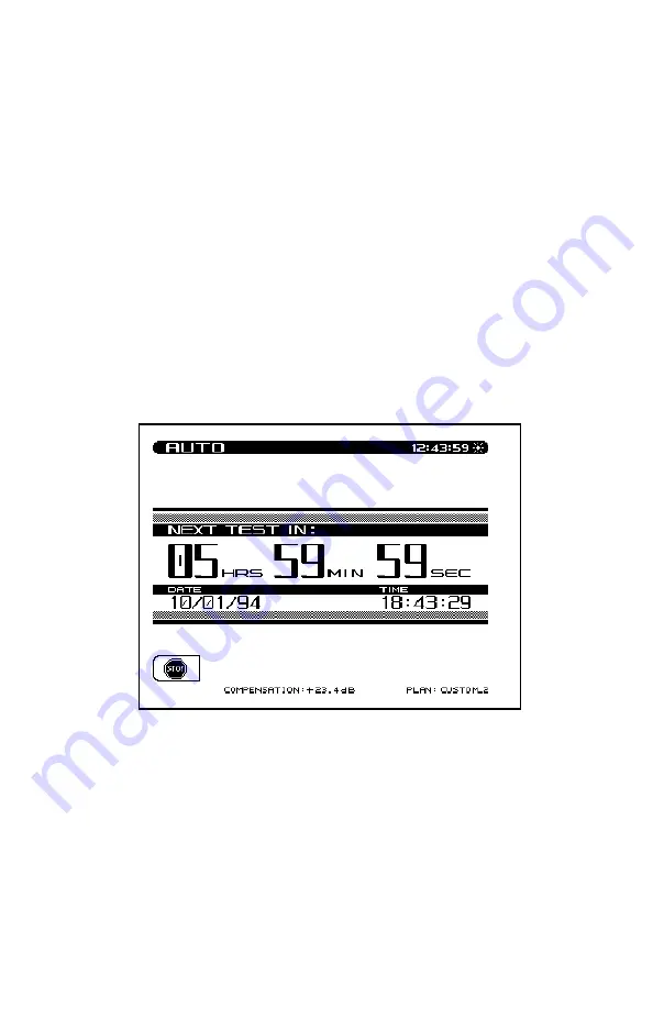
immediately, the "Auto Test In Progress" screen is displayed. When
the unit is between testing intervals, the following screen is dis-
played:

When the unit is between testing intervals it will enter a sleep mode
in order to conserve battery life. All other unit functions are disabled
during the performance of the Auto Test.

Содержание 3ST

Страница 1: ...607 E Mail catvsupport wavetek com Internet http www wavetek com 11 96 Rev I Manual Part No 6510 00 0273 This document contains information proprietary to Wavetek The information in this document is n...

Страница 2: ...used by improper storage improperinstallation unauthorizedmodification misuse neglect inadequatemaintenance accidentorforanyProductwhichhasbeenrepairedoralteredbyanyoneotherthanWavetek or its authoriz...

Страница 3: ...Spectrum Mode 1 4 1 2 8 Intermodulation Distortion 1 4 1 2 9 Depth of Modulation 1 5 1 2 10 Serial Interface 1 5 1 2 11 General 1 5 1 2 12 Powering 1 5 1 2 13 Standard Accessories 1 6 1 2 14 Options 1...

Страница 4: ...6 SECTION 4 OPERATION HOW TO USE THE 3ST TRANSMITTER 4 1 INTRODUCTION 4 1 4 2 STEALTH SWEEP START UP PROCEDURE 4 1 4 3 SETUP 4 4 4 3 1 General Setup 4 5 4 3 2 Measurement Setup 4 8 4 3 3 How To Setup...

Страница 5: ...RODUCTION 5 1 5 1 1 Wavetek Stealth Reverse Sweep Concept 5 1 5 1 2 Basic Reverse Sweep Procedure 5 1 5 1 3 Interfacing With Different Network Architectures 5 2 5 2 HOW TO SETUP FOR REVERSE SWEEPING 5...

Страница 6: ...s to the 3SR Receiver with every sweep update In this way any headend level changes are compensated by the receiver to maintain the utmost measurement accuracy Sweep response measurements won t be aff...

Страница 7: ...tandard 19 rack mount unit that weighs approximately fifteen pounds Its 320 X 240 dot matrix LCD shows measurement data in both graphical and numerical form 1 2 SPECIFICATIONS 1 2 1 Frequency Range 5...

Страница 8: ...racteristics Video Carrier Level dBmV Carrier to Noise Range 0 10 20 30 40 50 60 10 0 10 14 24 Specified results with the measurement offset within 2 to 3 MHz range above the video carrier Resolution...

Страница 9: ...MHz div Sweep Rates 2 seconds 50 5 MHz Display Scaling and Range 0 5 1 2 5 and 10 dB division 6 vertical divisions Spurious Free Dynamic Range 60 dB typical specifications 1 2 8 Intermodulation Disto...

Страница 10: ...n 0 5 at 85 1 2 10 Serial Interface Serial RS232 Epson IBM Printers 1 2 11 General Log Linearity 0 5 dB typical Flatness 0 5 dB 25 C 20 dBmV Dimensions Transmitter 3ST 48 3 cm W x 13 3 cm H x 35 6 cm...

Страница 11: ...er 120VAC to 18VDC 1019 00 0437 Charger Adapter 220VAC to 18 VDC SBC 1 Charger for one spare Stealth Battery Cartridge SBC 6 Charger for up to six spare Stealth Battery Cartridges 1217 50 0151 Stealth...

Страница 12: ...dBmV to 20 to 50 dBmV To determine which transmitter output range is available on your unit access the Status screen by pressing the FCN key followed by the status second function key If Enhanced Outp...

Страница 13: ...tative 2 3 INSTALLATION Proper installation of the Transmitter is essential to correct operation of the system The transmitter is typically installed in a headend rack There are two different options...

Страница 14: ...ttenuator pad Combining Network Stealth Transmitter IN OUT DC a DC b Sys Stealth Receiver IN An alternate method would be to insert the 3ST Transmitter output at one of the combining network inputs an...

Страница 15: ...operation of the 3ST Transmitter Stealth to Stealth and a Serial Printer cable The following information describes each of the associated cables Stealth to Stealth The Stealth to Stealth cable 1217 5...

Страница 16: ...2 4 Serial Printer Cable The Serial Printer Cable 1217 50 0151 can be used to print data directly from the 3ST Transmitter Tx Rx GND DTR Rx Tx DTR GND DSR CTS...

Страница 17: ...it to be damaged or incomplete in any way phone Wavetek immediately Save the shipping carton and packing material in the event that you have to return it FOR CUSTOMER SERVICE call WAVETEK 800 851 1198...

Страница 18: ...dBmV to 20 to 50 dBmV To determine which transmitter output range is available on your unit access the Status screen by pressing the FCN key followed by the status second function key If Enhanced Outp...

Страница 19: ...ad The keypad includes eight Soft keys eight Measurement Mode selection keys four Support Mode selection keys four Arrow keys sixteen Numeric Entry keys 3 2 1 Soft Keys There are a total of eight vert...

Страница 20: ...below the display LEVEL Signal level measurements on individual channels are made by entering a specific channel number and pressing the channel key Measurements can also be made by selecting the carr...

Страница 21: ...aph format NOTE Telemetry occurs only while the unit is in Sweep mode Selecting another mode will result in a loss of telemetry to any Receivers connected to the system C N Measures the C N carrier to...

Страница 22: ...t files Auto This function provides automated FCC 24 hour testing capabilities Setup The setup functions are used to set or adjust the operating parameters of the unit Print Allows the user to print t...

Страница 23: ...to enter data as needed during the operation of the unit There are three indicators associated with keypad entry These indicators appear in the title bar to the left of the time The three are as follo...

Страница 24: ...nated by pressing the ENTER key Numeric Entry Mode In the numeric entry mode only the numerals 0 through 9 and the decimal point can be entered When negative values are allowed the FCN key sequence to...

Страница 25: ...imulta neously to the receiver It also measures its own injected sweep carrier In order to do this the sweep must be injected prior to the tap which samples the system signal for the transmitter s mea...

Страница 26: ...he SETUP key 2 Press the Channel Plan soft key and cursor down the menu to Build Channel Plan 3 Press the ENTER key and you will be prompted at the first step to name the channel plan to be built The...

Страница 27: ...channels are properly designated as video or single carriers FM signals may be entered as channels but must be designated as Single Carriers At this time be sure to edit each scrambled channel to ensu...

Страница 28: ...f the reference measurement After the reference is stored press the SWEEP key and the sweep will be compared to the reference you just stored The response should be relatively smooth the D marker shou...

Страница 29: ...e the Up and Down soft keys to scroll to additional setup items When lists are being displayed the up arrow soft key dims when the first item in the list is reached and the down arrow soft key dims up...

Страница 30: ...a scale from 1 15 Use the UP and DOWN arrow keys to adjust the contrast Backlight Time out Period An additional feature is an automatic Backlight Time out The time out period is programmable to always...

Страница 31: ...bits 1 stop bit no parity flow control hardware handshaking A serial to parallel converter such as the one manufactured by Black Box Corp is required for printing to a parallel printer The setup is th...

Страница 32: ...stics Press the ENTER key to enter the diagnostic mode The diagnostic mode allows the user to reset the unit to all factory default settings Warning All files and references will be lost when resettin...

Страница 33: ...MHz in 10 kHz steps Fundamental Hum Frequency The fundamental hum frequency to be measured can be selected using the UP and DOWN arrow keys 60 Hz 50 Hz Auto When Auto is selected the unit will automa...

Страница 34: ...splay the system noise level when the calibration is complete 4 3 3 How To Setup Your Channel Plan The procedure explained in Section 4 2 should be performed when first using the Model 3ST Transmitter...

Страница 35: ...Plan name The Channel Plan that the plan was based on The number of enabled channels Date the plan was last modified Video Signal Type The type of video signal to be measured can be selected using th...

Страница 36: ...all channels in the selected fixed plan until the stop frequency is reached This opera tion can be terminated by pressing the STOP soft key When com pleted individual channels contained in the newly b...

Страница 37: ...4 13 Use the UP or DOWN arrow keys to select the channel that you wish to edit Press the EDIT soft key to view and edit the following parameters...

Страница 38: ...video plus two independent audio carriers Single Carrier Can be used for an FM or data carrier Sweep Insertion Point Used to insert sweep points into vacant spectrum areas Digital Carrier Can be used...

Страница 39: ...rement BW selection The bandwidth can be adjusted by using the UP and DOWN arrow keys or by entering a value using the numeric keypad and then pressing the ENTER key The FCC specification for C N meas...

Страница 40: ...the plan or deleting existing channels from the plan Press the Exit soft key to return to the Edit Channel Parameters display Delete Unused Channels Once the channel plan has been built unused channe...

Страница 41: ...o 827 62 882 63 to 882 87 lower to 882 62 938 13 to 938 37 lower to 938 12 385 63 to 385 87 lower to 385 62 620 13 to 620 37 lower to 620 12 703 63 to 703 87 lower to 703 62 524 38 to 525 62 raise to...

Страница 42: ...o Test measurements If a test is selected the None soft key is displayed If no tests are selected for a particular channel then the All soft key is displayed Edit Limits The Edit Limits function works...

Страница 43: ...eneral Setup screen A baud rate of 19 2K is recommended for uploading plans Select Copy Remote Plan from the menu and press the ENTER key A list of plans located in the remote units memory will appear...

Страница 44: ...o close to the diplex filter cut off frequency in that roll off may attenuate the telemetry signal to the degree that communication fails This same caution applies to placing the signal in the high en...

Страница 45: ...N arrow keys to include Yes or exclude No audio carriers Enable or Disable Reverse Sweep When Reverse Sweep is enabled both Forward and Reverse sweep ing can be performed Only Forward sweeping is poss...

Страница 46: ...elect the Reverse Sweep Plans option and then press the ENTER key Refer to section 5 for detailed operation 4 4 HOW TO PERFORM LEVEL MEASUREMENTS Signal levels are measured in the Level and Scan Modes...

Страница 47: ...el or Frequency When the level mode is selected the unit can be tuned by channel or frequency When in the channel mode the channel and channel label will appear at the top of the display The left and...

Страница 48: ...spectrum that are used for Automatic Gain Control AGC or Automatic Slope Control ASC In the amplifier balancing process these signals are measured and adjusted to specification Before making an adjust...

Страница 49: ...T key is pressed the screen will automatically display up to nine video carrier levels that were defined in the Edit Channel Parameters portion of the Channel Plan Setup menu The UP and DOWN arrow key...

Страница 50: ...oft key will automatically set the reference level for an optimum Tilt display The FCN Scale key can also be used to automatically set the reference level 4 6 SCAN MODE Use the Scan mode to get a good...

Страница 51: ...arrow keys to select a scale that will provide the best viewing of the carrier levels To adjust the Ref Level press the Ref Level soft key Now the Ref Level can be changed by using the UP and DOWN ar...

Страница 52: ...re available in the Scan mode normal and fast The scan rate is selected in the Measurement Setup menu The Fast scan feature allows for rapid scan displays while sacrificing accuracy as much as 2 dB on...

Страница 53: ...M soft key This performs a limit check of all channels contained within the scan and reports an overall pass fail conclusion The aggregate limit check is not performed with each scan update however a...

Страница 54: ...ode the carrier to noise ratio of the tuned channel or frequency is displayed The C N measurement bandwidth and the frequency offset for the noise measurement may be controlled from the screen A propr...

Страница 55: ...4 200 MHz CATV organizations outside of the United States may have different requirements Noise Offset Frequency Adjustments The frequency at which the noise level is measured is the Carrier frequenc...

Страница 56: ...120 50 100 Hz or 1 000 Hz filters for this measurement to help in troubleshooting A 60 Hz modulation component suggests a possible corroded connec tor a 120 Hz component tends to indicate a possible f...

Страница 57: ...TION This function allows you to monitor the video depth of modulation in graphical and precise numerical format A marker is placed at the optimal modulation level NTSC 87 5 PAL 90 to assist techni ci...

Страница 58: ...ER MODE The spectrum analyzer display provides a view of the system spectrum with variable spans from 50 MHz to 3 MHz and a dynamic range of better than 60 dB When the Spectrum key is pressed the foll...

Страница 59: ...e adjusted using the cursor keys or by entering a numeric value followed by the enter key The scale parameter 1 2 5 10 dB Div can only be adjusted with the cursor keys For example if the reference lev...

Страница 60: ...f the display and reads the delta indicated at the bottom of the screen The FCC requirement is a window of 2 0 dB which means the delta should be 4 dB How To Make CSO CTB Measurements CSO Composite Se...

Страница 61: ...4 37 Press the OK soft key once the carrier has been turned off The CSO CTB measurement is now displayed...

Страница 62: ...f the second and third order beats The worst case CSO value is highlighted and is the overall CSO value Press the CSO Setup soft key to adjust the offset values for the CSO measurement Using the Up an...

Страница 63: ...eep mode operates the same as the Scan mode with the following exceptions Sweep telemetry is transmitted Sweep points are injected Sweep point levels are displayed in the graph NOTE Sweep telemetry wi...

Страница 64: ...eature allows the user to store sweep spectrum and scan measurements To store a measurement press the File key while taking the measurement Press the Store Measure ment soft key to access the measurem...

Страница 65: ...le to be viewed Once selected press the View soft key Scan measurements can be stored but can only be viewed printed using the Stealthware Data Analysis software Once a file is selected it can be prin...

Страница 66: ...ecific test point location parameters used in the Auto Test report The Test Locations can be created directly on the Stealth unit or using the SteathWare Data Analysis software and downloaded to the S...

Страница 67: ...4 43 Press the New soft key to create a new Test Location file The unit will then prompt for a file name Once a name is entered press the OK soft key to execute the operation...

Страница 68: ...ker Config 1 9 1 5 Trunk Termination NO YES NO 6 Voltage Setting LOW MID HIGH 7 Rev Pad 100 0 100 0 0 0 dB 8 Rev Equalizer 100 0 100 0 0 0 dB 9 Fwd Pad 100 0 100 0 0 0 dB 10 Fwd Equalizer 100 0 100 0...

Страница 69: ...ameters have been edited press the OK soft key The Delete soft key is used to delete a specific location file 4 13 2 How To Perform An Auto Test The Auto Test mode provides automated FCC 24 hour testi...

Страница 70: ...the Up and Down arrow keys select an Auto Test location Select NONE if location information is not desired Press the OK soft key when completed To create a new Auto Test location press the New soft k...

Страница 71: ...made and the Save soft key is not pressed the changes will only affect the Auto Test that is about to be performed Press the OK soft key when completed Test Point Type Use the Up and Down arrow keys...

Страница 72: ...e the numeric entry keys to enter the following system voltage measurements AC Voltage DC Voltage regulated DC Voltage unregulated The voltage measurements are printed in the Auto Test report Press th...

Страница 73: ...is used to account for loses associated with certain amplifiers Use the UP and DOWN arrow keys or the numeric entry keys to enter the Test Point Compensation 100 0 to 100 0 dB in 0 1 dB steps Press th...

Страница 74: ...commence the Auto Test Press the Scheduled soft key to perform the Auto Test repeatedly at scheduled intervals Immediate If the Immediate mode is selected the unit will commence the Auto Test sequenc...

Страница 75: ...ng performed i e Level C N Hum or Modulation is indicated on the screen A bar graph showing the percentage of completion is dis played Scheduled If the Scheduled mode is selected the start stop and in...

Страница 76: ...prompt you to enter the ambient temperature The temperature displayed is the temperature sensed by the unit Use the numeric entry keys to enter the ambient temperature Press the OK soft key when the...

Страница 77: ...key is available to print all intervals from all files in the directory to the printer The Info soft key displays the Test Location Characteristics for the selected file A table with all testing inte...

Страница 78: ...lure of the measurements taken during that interval A check mark indicates that all measurements were within the specified limits To comply with FCC 24 hour testing requirements the 24hr Report soft k...

Страница 79: ...0 05 00 00 11 00 00 Temp 75 F 61 F 59 F 83 F Video Video Video Video 24 Hr Chan Level Level Level Level Deviation dBmV dBmV dBmV dBmV dB 2 9 6 8 8 17 7 LO 10 7 28 4 HI 3 9 9 8 6 5 8 LO 8 9 15 7 HI 4 9...

Страница 80: ...urement was out of specifica tion Each interval can be selected and viewed as desired Use the Up and Down arrow soft keys followed by the View soft key to view specific interval test results The test...

Страница 81: ...tion measurements When viewing the list of C N Hum and Modulation measurements the following symbols will replace the measurement value if an error occurred UNDER under range OVER over range ERROR syn...

Страница 82: ...3 TNN 5 8 LO 13 9 8 1 4 USA 2 9 LO 15 6 12 7 0 9 5 ESPN 0 1 16 1 16 2 48 2 6 MTV 7 9 20 3 28 2 HI 88 2 7 FMLY 9 9 10 6 20 5 HI 8 CMDY 6 9 11 5 18 4 HI 12 7 9 LIFE 9 1 11 1 20 2 HI 10 VH1 8 5 13 3 21...

Страница 83: ...decide if unwanted files should to be deleted to make more memory available for newer files 1 Specification Change The transmitter output is being changed from 10 to 40 dBmV to 20 to 50 dBmV To determ...

Страница 84: ...he sweep response as measured in the headend on its LCD Only one receiver at a time can perform reverse sweep ing If additional receivers attempt to sweep a message is displayed The only effect on rec...

Страница 85: ...to the 3ST transmitter The system signals along with the transmitted signals are tapped off and coupled together with the reverse signals using a splitter This enables the 3ST transmitter to receive b...

Страница 86: ...the 3ST Transmitter This provides optimal isolation between forward paths and minimal insertion loss The connection at the node may be as shown in figure 4 Notice that in this configuration the forwa...

Страница 87: ...s Figure 4 Fiber Node Test Point Connections Dual Cable Network Another possible though rare network configuration is the Dual Cable Network in which a full bandwidth is used for both forward and reve...

Страница 88: ...tter out to the furthest extremity and sweep the reverse portion 5 2 HOW TO SETUP FOR REVERSE SWEEPING To setup the Reverse Sweep on the 3ST press the SETUP key and select the Sweep Transmitter option...

Страница 89: ...verse telemetry carrier should be carefully selected such that it will not interfere with any existing carriers on the reverse plant 5 2 3 Access Reverse Sweep Plans Reverse Sweep Plans are used to de...

Страница 90: ...eep Plan You will be asked to enter a name for the plan that you are creating Use the alphanumeric keys followed by the ENTER key Then press the OK soft key to continue NOTE A warning message will app...

Страница 91: ...p point in the plan Use the numeric keys followed by the ENTER key Then press the OK soft key to continue The Interval is entered next This interval determines the spacing between sweep points Use the...

Страница 92: ...Finally you are asked to enter the Stop Frequency There will be no sweep points generated beyond the Stop Frequency Use the numeric keys followed by the ENTER key Then press the OK soft key to contin...

Страница 93: ...e Sweep Plan If desired the selected Reverse Sweep Plan can be viewed and modified IMPORTANT You should verify that none of the sweep points contained within the Reverse Sweep Plan will interfere with...

Страница 94: ...int use the up or down arrow to select the point to be removed then press the Delete soft key Press the Add soft key to insert a new sweep point into the plan The new point will be at the same frequen...

Страница 95: ...the Stealth 3ST The following is a list of all status indicators icons and an explanation of each The status indicators are displayed in the title bar as shown in the example below Video Carrier Audio...

Страница 96: ...ry frequencies are matched Message SORRY The selected reference cannot be used Condition The channel plan has been changed or a different channel plan has been selected since storing the reference Res...

Страница 97: ...dy exists Overwrite Condition A reference with the same name currently exists Response Overwrite the existing reference or choose another name Message SORRY This is an invalid name Please try again Co...

Страница 98: ...error has occurred Condition A system error has been detected Response Restart the unit and try again Message ERROR There is no response from the printer Condition The printer is not responding to the...

Страница 99: ...ailure Response Delete the corrupted file and select another sweep file Message ERROR A system error has occurred Please select another mode Condition A system error has been detected Response Select...

Страница 100: ...h the same name currently exists Response Overwrite or choose another name Message SORRY This is the name of a fixed plan and cannot be used Condition An attempt was made to name a channel plan with t...

Страница 101: ...cel Message SORRY There is not enough memory to store the new plan Condition Memory is currently at maximum capacity Response Delete unwanted files to make more memory available Message WARNING There...

Страница 102: ...mbled channel Message ERROR Hum cannot be measured on a scrambled channel Condition A channel that has been programmed as scrambled in setup has been selected in Hum mode Response Select a channel tha...

Отзывы: