11
6.1.3
Serial Mode (over RS485)
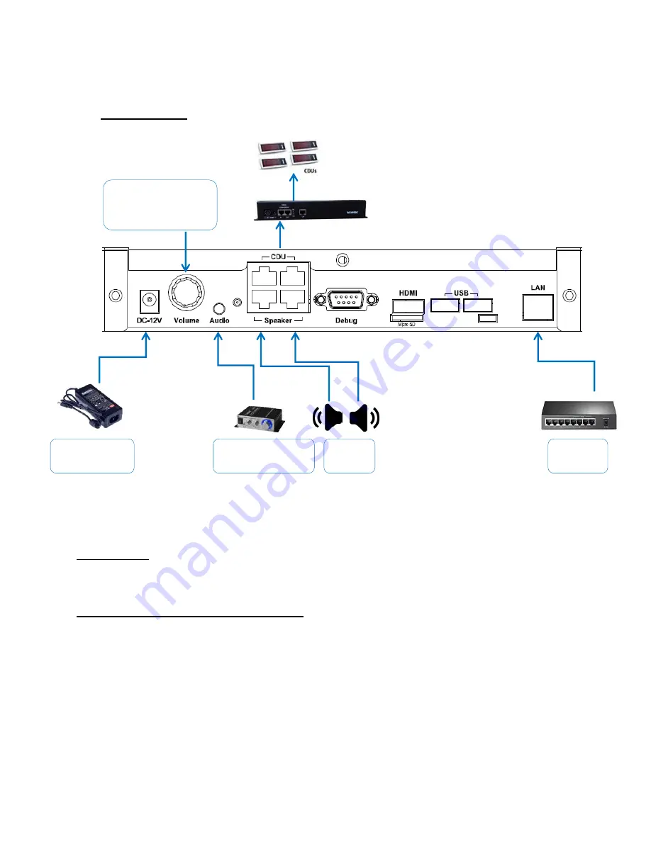
Wiring Diagram:
Description:
Connect the Spectra controller as shown in wiring diagram above.
1) Driving displays (CDUs, SDUs and PDUs):
In order to drive displays connect one end of patch cord (Straight cable – RJ45 on both
ends) to port marked “CDU” in Spectra and other end to Active Hub/TCP Active Hub port
marked “IN”.
All the End Devices (Displays) can be connected to any of the 16 output ports of Active Hub.
Refer to Active Hub installation guide for further details, ensure that the DIP switch setting
of the Active Hub is as per the document and that termination is disabled.
To connect external
amplifier or headphone
(optional)
Power adapter
12V 3.43A
2 x 8Ω
speaker
Ethernet
switch
Volume Knob - Rotate
clockwise to increase
volume
Содержание Spectra
Страница 1: ...Wavetec Pvt Ltd Haider Ali 9 4 2020 Spectra Controller Installation Guide Rev 1 0...
Страница 2: ...2 Document History Revision Date Comments Prepared By 1 0 April 09 2020 First Release Haider Ali...
Страница 13: ...13 7 Debugging 8 Upgrading Spectra Updating Patch For upgrading system For upgrading system...
Страница 14: ...14 9 External Amplifier Connections 2 x 4 8 speaker Power adapter 12V Audio Aux Cable 3 5mm...
Страница 15: ...15 10 Wiring Diagram with whole system...
Страница 16: ...16...


