


© 2019
www.teamWavelength.com
10
QCL OEM SERIES LOW-NOISE DRIVER
•
Connect the voltmeter to the Current Limit Monitor,
pins J1:4 (positive) and J1:3 (negative/gnd).
• Adjust the LIMIT trimpot until the Current Limit Monitor
voltage matches the calculated V
LIMIT
value.
The procedure detailed here results in a practical current
limit that is somewhat below the limit calculated using the
transfer function. To set the current limit more accurately,
refer to
page 15
.
ADJUST THE OUTPUT CURRENT
USING THE SETPOINT MONITOR
The DC current setpoint is set by adjusting the SET trimpot
on the front panel:
•
Refer to the datasheet for your QCL to find the operating
current, then calculate the Current Setpoint Monitor
voltage using this equation and referencing
Table 3 on
page 4
for the transfer function:
V
SET_MON
= (I
OUT
/ Transfer Function) – 0.080 (V)
•
Connect the voltmeter to the Current Setpoint Monitor,
pins J1:6 (positive) and J1:3 (negative/gnd).
• Adjust the SET trimpot until the V
SET_MON
value on the
voltmeter matches the calculated V
SET_ MON
value.
•
The SET_MON voltage is offset from the OUT_MON
voltage by approximately 80 mV. To improve output
setpoint accuracy, follow the procedure outlined in the
next section.
ADJUST THE OUTPUT CURRENT
USING THE CURRENT OUTPUT MONITOR
The DC current setpoint is set by adjusting the SET trimpot
on the front panel:
•
Refer to the datasheet for your QCL to find the operating
current, then calculate the Current Output Monitor
voltage using this equation and referencing
Table 3 on
page 4
for the transfer function:
V
OUT_MON
= I
OUT
/ Transfer Function (V)
•
Connect the voltmeter to the Current Output Monitor,
pins J1:5 (positive) and J1:3 (negative/gnd).
• Switch on the driver output usng the ENABLE switch.
• Adjust the SET trimpot until the V
OUT_MON
value on the
voltmeter matches the calculated V
OUT_MON
value.
•
To further protect the QCL, the current limit can be
decreased to just above the setpoint value by adjusting
the LIMIT trimpot until the voltage just begins to
decrease. Then increase the limit until the voltmeter
reads the correct V
OUT_MON
value again.
Once the driver is configured, disable the output then switch
off the driver. Finally, switch off the power supplies.
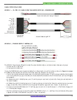
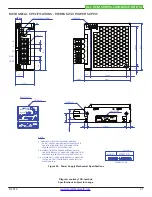
CONFIGURE THE +5V AUX JUMPER
The QCL driver can be configured to provide a 5 VDC output
on pin J5:1.
Changing the configuration requires opening the QCL
driver case: In an ESD-safe environment, remove the eight
Phillips screws located around the perimeter of the base of
the unit; there are two screws on each side. Next remove
the baseplate; the fit is intentionally tight and it will take
some effort to remove the baseplate.
Refer to
Figure 5 on page 11
for the jumper location.
Removing the jumper pin disables the +5V AUX output;
placing the jumper over both pins of the header connects
pin J5:1 to the +5V AUX supply. Pin J5:2 is Ground and
is always connected to ground, regardless of the jumper
position.
When the QCL driver is delivered, the +5 AUX output is
Disabled.
Avoid driving noisy external circuits with the +5V AUX
output; the external circuit may impact the QCL driver
output noise level if adequate precautions are not taken to
filter electronic noise.