


© 2018
12
LDTC2/2 LASER DIODE DRIVER AND TEMPERATURE CONTROLLER
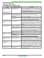
DISABLING THE OUTPUT CURRENT
The output current can be enabled and disabled as shown in
using the on-board toggle switch. The Enable LED
lights green when laser diode current is enabled.
ON
OFF
LD ENABLE
TOGGLE
SWITCH
LD Enable
Figure 9. Use the on-board toggle switch to enable or
disable output current to the laser diode.
A remote voltage signal can be used to control the output
status of the laser driver using the laser diode shutdown
(LD SHD) pin. Float or connect a zero Volt signal to LD SHD
(Pin 3 on Connector J2) to ENABLE output current to the
laser diode. A voltage level greater than 3 V, but less than 5
V, will DISABLE output current to the laser diode. This diode
was designed for TTL inputs.
The external LD SHD signal to Pin 3 has complete control
when the on-board LD Enable switch is in the ENABLE
position.
!
Do not insert or remove the laser diode from
the circuit while power is applied to the LDTC.
The laser diode may be damaged or destroyed.
!
Always turn off the power to the unit prior
to making any circuit modifications and always
use proper operator grounding and anti-
static procedures.
MONITOR LASER DIODE OR PHOTODIODE
CURRENT
provides a transfer function for converting the
voltage output of LD I M (Laser Diode Current Monitor - Pin 8
of Connector J2) to the amount of current flowing through
the laser diode.
Equation 1. Laser Diode Forward Current Measurement
I
LD DEFAULT
= 1.25
·
V
LD I M
provides a transfer function for converting the
voltage output of LD P M (Laser Diode Power Monitor - Pin 7
of Connector J2) to the amount of current flowing through
the photodiode.
Equation 2. Monitor Photodiode Current Measurements in
Constant Power Mode
2 mA PD Range:
I
PD
= 0.001
·
V
LD P M
200 μA PD Range:
I
PD
= 0.0001
·
V
LD P M
Photodiode current can be monitored in Constant Current
Mode by monitoring J2 Pin 2 (PD MON) with a voltmeter.
(NOTE: Pin 1 & Pin 2 on J2 are not available on Rev. A.)
The
photodiode current is then given by
:
Equation 3. Monitor Photodiode Current Measurements in
Constant Current Mode
2 mA PD Range:
I
PD
= 0.002
·
V
PD MON
200 μA PD Range:
I
PD
= 0.0002
·
V
PD MON
NOTE: Available Rev. B and later.
NOTE: LD P MON has a gain of 2.
PD MON has a gain of 1.
Determining Revision:
The product revision is indicated
within the serial number. Find the serial number labeled
on the PCB. Revision is the third character. Example:
00
B
1730002 would be Revision B of the LDTC2/2.