Wavelength Electronics LDTC2/2 Скачать руководство пользователя страница 10

www.teamwavelength.com

© 2005  

PRELIMINARY

LDTC2/2

PAGE 10

LDTC2/2-00400-A  Rev A

WTC OPERATION, continued

4.  PROPORTIONAL GAIN AND 
 

INTEGRATOR TIME CONSTANT - 

 PI 

TERMS

The LDTC2/2 is confi gured to the mid-range 
positions appropriate for most laser diode loads.  
To adjust these parameters to optimize the 
temperature control system time to temperature or 
stability, contact Wavelength.

5.  POWER SUPPLY SELECTION

The VDD voltage supply input is common to both 
the WLD3343 and the WTC3243.  This supply 
furnishes the voltage to the control electronics of 
the devices as well as the compliance voltage for 
the WLD3343 Laser Driver.  

The supply should be capable of providing at least 
3.0 Amps of current in applications that use a 
separate VS supply in the temperature control 
implementation.  Temperature control applications 
that tie VDD and VS together require a  VDD 
current capacity that equals the sum of the 
maximum TEC or Resistive Heater current, 
plus the maximum laser diode current, plus 
approximately 200 mA for the control electronics 
of the WTC3243 Temperature Controller and the 
WLD3343 Laser Driver, plus current to an optional 
fan.  Using the maximum potential of the WLD and 
WTC will not require more than 6.0 Amps.

VS is the voltage that is applied to the TEC 
or resistive heater.  This voltage should be high 
enough to supply the voltage required by the TEC 
or resistive heater plus the compliance required by 
the WTC.  The voltage available to the TEC will 
be from between 0.5 to 1.8V lower than VS.  To 
minimize power dissipation in the WTC, keep VS 
as low as possible.

Online Safe Operating Area (SOA) calculators 
are available for the WTC3243.  Calculate the 
maximum power dissipation of your design at  

http://www.teamwavelength.com/

tools/calculator/soa/defaulttc.htm


before applying 

power to the LDTC2/2.  

7.  MONITOR ACTUAL TEMP AND 
 SETPOINT

Pins 9 & 10 of Connector 2 are ACT T Monitor and 
SET T Monitor respectively.  Measure the actual 
sensor voltage across Pin 9 and Pin 12 (COM).  
For a 10k

 thermistor with 100

µ

A bias current, 

the resistance (in k

) is given by:

 R 

V

PIN 9

 / 0.1

To monitor the Setpoint Voltage used by the WTC, 
use pins 10 and 12.  

For other sensor calculations, contact Wavelength.

6.  TEMPERATURE SETPOINT

Wavelength introduces a special setpoint circuit 
with the LDTC2/2.  An on-board trimpot (TSET) 
will adjust the voltage from 0.3V to 2.5V.  
Additionally, Pin 11 (R TC SET) & 12 (COM) of 
Connector 2 will accept a DAC voltage (from 0.3 
to 2.5V).  The new feature - the “Failsafe Setpoint”  
will default the setpoint to 1V (~25°C for a 10k


thermistor) if the chosen signal (from pot or DAC) 
falls below 0.3V.  

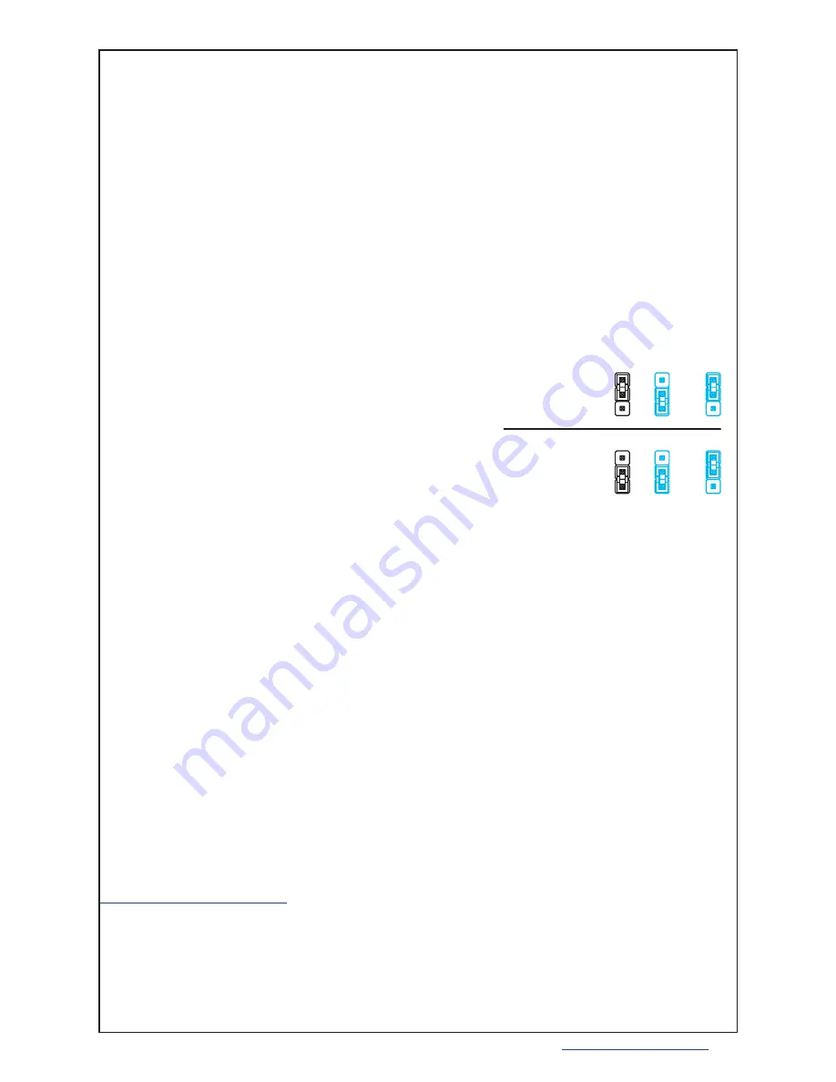
A jumper set lets you choose to use only the 
on-board potentiometer or the external voltage.  

JP1 confi gures the Remote Temperature Setpoint 
choice.  There is about 100mV of hysteresis built 
into the default voltage.  The input impedance of 
the R TC SET is greater than 20k

 and is fully 

buffered.  

If you use a different sensor or would prefer a 
different default voltage, contact Wavelength.

8.  ENABLE CURRENT TO TEC

Output current is supplied to the load as soon as 
power is applied to the controller.  The Power LED 
indicator will light GREEN when power is applied.

ExtTset

Vset

Vset

PDset

ExtTset

Vset

PDset

Use On-board
trimpot only

Use Extermal
Voltage

Figure 1

Source of setpoint

Содержание LDTC2/2

Страница 1: ...er laser diodes for medical diagnostic equipment remote sensing and analytical instrumentation Combine the drive power of the WLD3343 with the temperature stability of the WTC3243 FEATURES Small packa...

Страница 2: ...LED Remote Enable CW 3 W 2 CCW 1 R5 500 1 2 3 JP3 HEADER 3 Sho w n i n CC LDC PDA PDC LDA VDD VDD VDD VDD Ext Vset LIM S2 EG2211 R23 1 00K R22 1 00K R17 1 00K 1 R7 1 00K R19 1 00K R21 4 99K R18 150 R1...

Страница 3: ...3 3V 1 U8 LM3480IM3 3 3 VCC Vset DAC VDD VDD VDD VCC VCC VCC R35 20 0K 1 2 3 4 5 6 7 8 9 10 11 12 J2 CON12 ACT T SET T GND ACT T SET T Common Common TEC TEC Sensor R33 10 0K R32 100K 1 2 3 J1 CON3 VDD...

Страница 4: ...VDD Current VDD supply quiescent INPUT Offset Voltage initial Imon Bias Current based on input Res of op amp Common Mode Range Common Mode Rejection Set point Power Supply Rejection THERMAL Heatsprea...

Страница 5: ...ps Pins 2 and 9 Pins 2 and 9 TAMBIENT 25 C Pins 2 and 9 TAMBIENT 25 C Pins 2 and 9 Full Temp Range Full Temperature Range Full Temperature Range 0 001 0 003 P 18 2 2 0 VS 0 7 VS 1 2 VS 1 6 VS 1 8 VS 1...

Страница 6: ...tage produced and transfer function to temperature is determined by the sensor chosen Connect a voltage source between Pin 11 VSET and Pin 12 GND to control the temperature setting remotely A default...

Страница 7: ...Vs VLoad and mark on the X axis Example 12 volts 5 volts 7 volts Point A 2 Determine the maximum current ILoad through the driver and mark on the Y axis 1 amp Point B 3 Draw a horizontal line through...

Страница 8: ...rrent ILoad through the controller and mark on theY axis 1 amp Point B 3 Draw a horizontal line through Point B across the chart Line BB 4 Draw a vertical line from Point A to the maximum current line...

Страница 9: ...ctric Thermoelectric Resistive Htr Resistive Htr TEC Connector 3 Pin 6 Thermoelectric positive wire Thermoelectric negative wire TEC Connector 3 Pin 7 Thermoelectric negative wire Thermoelectric posit...

Страница 10: ...n the WTC keep VS as low as possible Online Safe Operating Area SOA calculators are available for the WTC3243 Calculate the maximum power dissipation of your design at http www teamwavelength com tool...

Страница 11: ...t Sense Resistor RSENSE vs Maximum Laser Diode Current ILDMAX Figure 2 Location of RSENSE Equation 1 Calculating RSENSE Constant Power Mode WLD OPERATION Equation 2 Calculating The Power Rating For RS...

Страница 12: ...WTC3243 This supply furnishes the voltage to the control electronics of the devices as well as the compliance voltage for the WLD3343 Laser Driver The supply should be capable of providing at least 3...

Страница 13: ...D lights GREEN when Laser Diode Current is Enabled 7 MONITOR LASER DIODE OR PHOTODIODE CURRENT Equation3providesatransferfunctionforconverting the voltage output of LD I M Laser Diode Current Monitor...

Страница 14: ...connect an external voltage source to the R LD SET input The ISET trim pot provides a Set Point adjustment of between zero to 2 5 V To use an external voltage source summed with the voltage supplied...

Страница 15: ...rt laser diode packages that incorporate a built in sensor that is connected to or common with the laser case ground ORDERING INFORMATION LDTC2 2E LDTC2 2O For easy heasinking of Open Frame Model WEV...

Страница 16: ...MINARY LDTC2 2 PAGE 16 LDTC2 2 00400 A Rev A MECHANICAL SPECIFICATIONS LDTC2 2 E with enclosure 2 70 68 6 mm 0 15 3 8 mm 2 40 61 0 mm 4 80 121 9 mm 4 20 106 7 mm 0 15 3 8 mm 4 50 114 3 mm 0 13 3 2 mm...

Страница 17: ...PECIFICATIONS LDTC2 2 O Open Frame 1 1 1 CC CP S2 ON OFF Tset LIMA LIMB ILIM ISET D1 D2 J1 J2 J3 J4 ExtTset Vset PDset R2 R3 R4 R5 R6 0 15 3 8 mm 2 20 55 9 mm 0 15 3 8 mm 3 70 94 0 mm 0 062 1 6 mm 0 5...

Страница 18: ...DTC2 2 PAGE 18 LDTC2 2 00400 A Rev A HEATSINK FOOTPRINT 0 78 19 8 mm 0 945 24 0 mm 0 68 17 2 mm 0 946 24 0 mm 2 40 60 9 mm 0 945 24 0 mm 1 25 31 7 mm 0 156 4 0 mm 4 40 tapped holes in device 0 15 3 8...

Страница 19: ...ORANGE GRN W BLK WHT W BLK BLACK RED W BLK RED ORG W BLK GREEN 1 10 WIRE COLOR BLACK WHITE BLUE RED GREEN RED W BLK ORANGE WHT W BLK ORG W BLK GRN W BLK LDTC2 2 SERIES WCB 302 I O CABLE PIN 1 SP1 2 SP...

Страница 20: ...lusive or exclusive of any other life support device CERTIFICATION AND WARRANTY CERTIFICATION Wavelength Electronics WEI certifies that this product met it s published specifications at the time of sh...

Отзывы: