
6/19/2009
10739
r1
Please
Recycle
2800 De La Cruz Blvd.
Santa Clara, CA 95050
Phone: 800.879.8585
www.wattstopper.com
TROUBLESHOOTING
Loads do not operate as expected.
LEDs on a switch or
sensor don’t light
1. Check to see that the the device is connected to the DLM local network.
2. Check for 24VDC input to the device: Plug in a different DLM device at the device location. If
the device does not power up, 24VDC is not present.
• Check the high voltage connections to the room controller and/or plug load controller(s).
• If high voltage connections are good and high voltage is present, recheck local network
connections between the device and the room controller and/or plug load controller(s).
The wrong lights and plug
loads are controlled
1. Configure the switch buttons and sensors to control the desired loads using the Push n’
Learn adjustment procedure.
LEDs turn ON and OFF but
load doesn’t switch
1. Make sure DLM local network is not in PnL.
2. Check load connections to room controllers and/or plug load controllers.
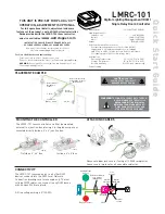
Load ON/OFF button
Blue LED ON when
load is ON
Config button &
red LED
OPTIONAL UNIT ADJUSTMENT -
PUSH n’ LEARN (PnL)
Load Selection Procedure
A configuration button (Config) allows access to our
patented Push n’ Learn™ technology to change binding
relationships between sensors,
switches and loads.
Step 1: Enter Push n’ Learn
Press and hold the Config button
(on any DLM device) for 3 seconds.
The red LED on the LMRC-101
begins to blink as does the red LED
on ALL other communicating devices
connected to the DLM local network.
The red LEDs continue to blink until you exit PnL mode.
All loads in the room turn OFF immediately after
entering PnL, then one load will turn ON. This is Load
#1, which is bound to switch button #1 and occupancy
sensors as part of the Plug n’ Go factory default setting.
All switch buttons and sensors that are bound to this
load have their blue LED solid ON.
Step 2: Load selection
Press and release the Config button to step through the
loads connected to the DLM local network. As each load
turns ON note the devices (switch buttons and sensors)
that are showing a bright solid blue LED. These devices
are currently bound to the load that is ON. The blue LED
on the room controller or plug load controller connected
to the load is also lit.
• To
unbind
a switch button from a load, press the
switch button while its blue LED is ON bright. The
blue LED goes dim to indicate the button no longer
controls the load that is currently ON.
• To
unbind
an occupancy sensor, press the up (
)
or
down (
) adjustment button while its blue LED is
ON. The blue LED turns OFF to indicate the sensor no
longer controls the load that is currently ON.
Pressing the switch or up (
)
or down (
) button again
while the load is ON
rebinds
the load to the button or
sensor and the blue LED illuminates brightly.
Step 3: Exit Push n’ Learn
Press and hold the Config button until the red LED turns
OFF, approximately 3 seconds.
PLUG n’ GO OPERATION (PnG)
Plug n’ Go supports the most energy efficient control
strategy. For example, if one load, one switch and one
occupancy sensor are connected to the DLM Local Network,
the system will operate the load Manual-On, Automatic-Off.
See DLM device Quick start guides to determine how each
device affects the PNG operation of the LMRC-101.
Load Control Arbitration
To take full advantage of automatic PnG configuration,
review these simple rules about load control arbitration.
After the room controllers are connected to the DLM Local
Network and powered up they automatically negotiate to
determine which controller becomes the Master and the
load numbers for each relay on the DLM Local Network.
The
Master
is the controller with the most load relays. If
more than one controller has the most relays, the one with
the highest serial number becomes the Master.
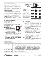
The LMRC-101 has
only one load. In a
DLM local network
with only LMRC-101
room controllers, the
LMRC-101 with the
highest serial number
is the Master, carrying
Load 1. The next
highest serial number
would have Load 2,
and so forth.
0458356155
Serial
Number
Room
Controller
Load
Control
0458356679
Master
1
0458356133
0458356133
LMRC-101
3
2
0458356155
LMRC-101
0458356679
LMRC-101


