13
KLSC20-KLSC25-KLSC32-IM-DE-W-UK-08-2021-Rev.0 | Part no. 10084836
EN
ENGLISH
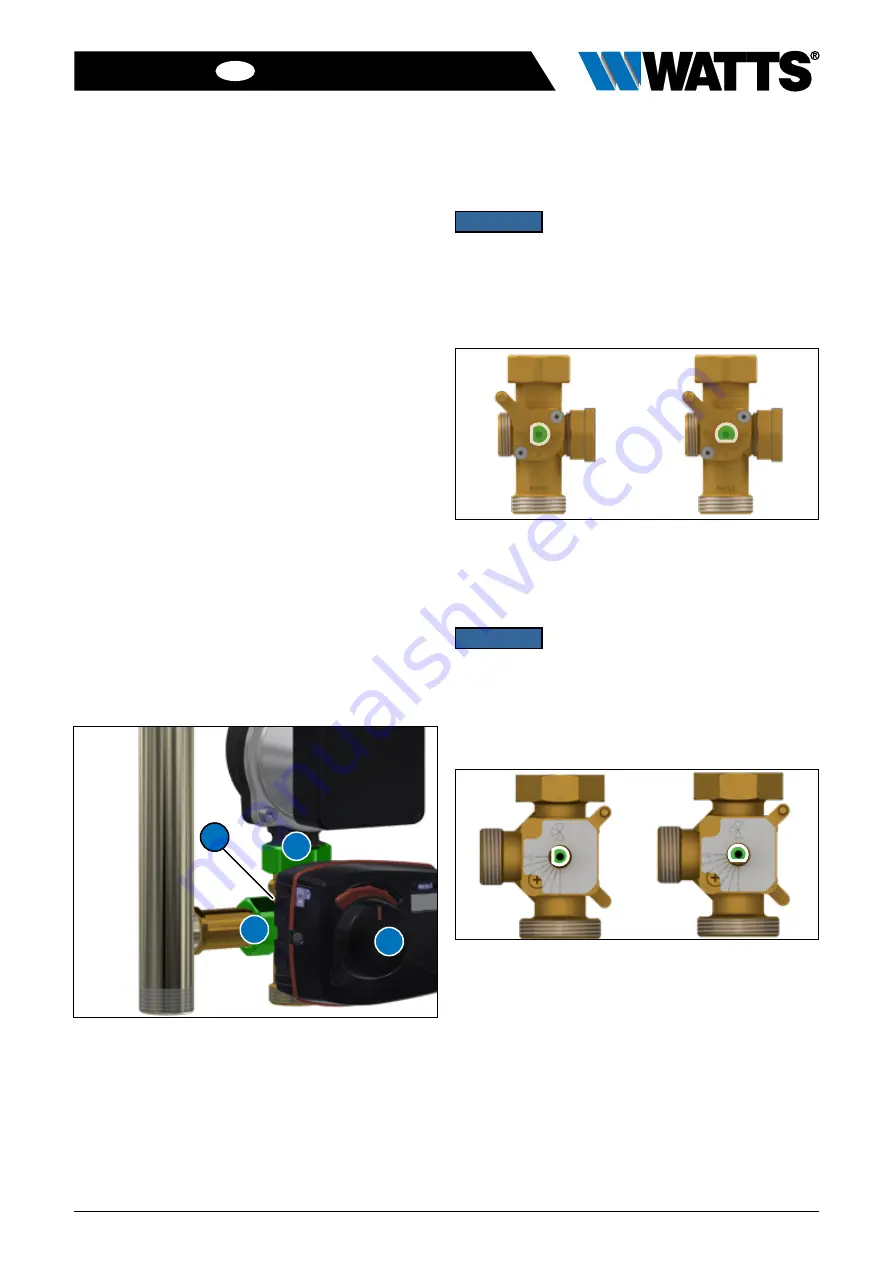
8.5 Removing the 3-way mixing valve
1. Disconnect the power supply and secure against
reconnection.
2. Remove the boiler charging unit (A) front cover.
3. Close all shut-off valves by rotating the thermometer
handle.
4. Remove the thermometer handles (B) and the intermediate
insulation (C).
5. Move the regulating insert (spindle) to centre position using
the lever on the actuator.
6. Remove the actuator (S).
7. Remove the mixer (M) by loosening the union nuts (X).
9
Instructions for fitting/removing the actuator can be
found in the relevant manufacturer’s manual.
8.6 Fitting the 3-way mixing valve
1. Replace the seals on the screw connections.
2. Insert the 3-way mixing valve (M) and tighten the nuts (see
Chapter 3 on page 4 for tightening torques).
3. Fit the actuator (S).
4. Slowly open the ball valve by turning the thermometer
handle (B).
5. Reconnect the power supply to the boiler charging unit.
6. Remove the thermometer handles (B).
7. Fit the intermediate insulation (C), thermometer handles (B)
and front cover (A).
9
Instructions for fitting/removing the actuator can be
found in the relevant manufacturer’s manual.
X
X
S
M
Fig. 8-2: Removing and fitting the 3-way mixing valve
8.7 3-way mixing valve actuator settings for
KLSC20
NOTICE
When reinstalling the actuator, make sure
the bearing shaft is in the correct position.
When setting up the regulating insert (spindle) for the first time,
refer to the images below.
Mixing valve open
Mixing valve closed
Fig. 8-3: Regulating insert (spindle) settings for KLSC20
8.8 3-way mixing valve actuator settings for
KLSC25 and KLSC32
NOTICE
When reinstalling the actuator, make sure
the bearing shaft is in the correct position.
When setting up the regulating insert (spindle) for the first time,
refer to the images below.
Mixing valve open
Mixing valve closed
Fig. 8-4: Regulating insert (spindle) settings for KLSC25 and KLSC32


