background image

IM-HKM40-50_HK40-50-DE-W-UK-12-2019-Rev.1 | Part no. 10083684

7

EN

ENGLISH

5  Installation and commissioning

Electricity!

Risk of death from electric shock!

•  Work on live parts must be carried out only by 

trained electricians.

•  Disconnect the power supply to the unit before 

carrying out any installation, maintenance, 
cleaning or repair work and secure it against 
reconnection.

Installation and commissioning of the pump 
unit must be carried out only by specialist 
personnel who have been duly trained and 
authorised by the manufacturer.

When carrying out repairs and replacing 
parts, the prescribed mounting positions and 
flow directions for the individual components 
to be replaced must be observed.

Material damage!

Opening shut-off valves quickly produces 
pressure surges.

•  Always open shut-off valves slowly and in a 

controlled manner.

5.1 Installation

Before installing the unit and starting it for the first time, 
check all screw fittings and retighten if necessary!

Torque

•  1½” screw fittings 130 Nm

•  2” screw fittings 190 Nm

Requirements

•  The fittings are preassembled at the factory; however, the 

tightness of the seal is to be checked before commissioning 
(pressure test).

5.2  Starting the unit

Requirements

•  The pump unit is fully installed.

1.  Connect the power supply (see separate pump 

documentation).


9

The pump unit automatically switches itself on when 
the power supply is connected.

2.  Bleed the heating system. 

The pump unit must be switched off during 
the bleed process.

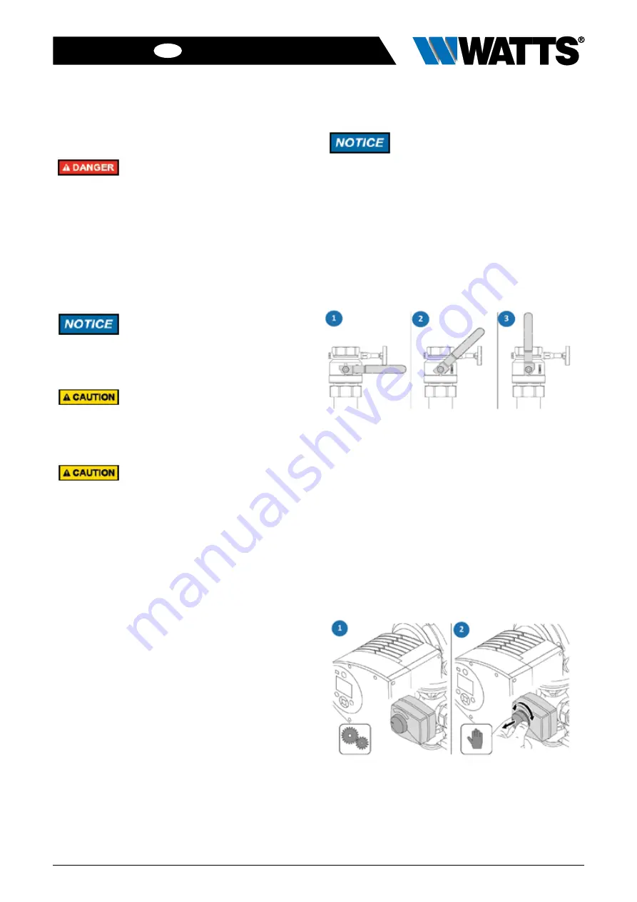
5.3  Lever position

The ball valve on the return circuit is fitted with a gravity brake. 
The gravity brake must be set to fill the system. 

•  Move the level to position (2).

•  The gravity brake is set and allows the system to be bled.

•  Fill the system.

1

Service setting: ball valve closed

2

Drain: ball valve half open (only included in the return 

circuit)

3

Operating position: ball valve open

5.4  Mixing valve operating position

•  Gently pull the knob on the mixing valve out. 

•  The mixing valve setting can be changed manually. 

•  Push the knob on the mixing valve back in to its original 

position.

•  The knob locks, mixing valve is in automatic setting.

1

Automatic setting

2

Manual operation

Содержание HK40 Series

Страница 1: ...HKM40 50 HK40 50 Series Pump units for distributing heating water in heating systems Installation and operating manual WattsWater de...

Страница 2: ...facturer 12 9 Warranty 12 1 General information 1 1 Important notes about the Installation and Operating Manual The operator is responsible for ensuring adherence to the local laws and regulations e g...

Страница 3: ...n Dimensions Width x height x depth with EPP shell 720 mm x 410 mm x 260 mm Weight DN40 DN50 HKM 40 50 Magna3 HKM 40 50 Stratos PARA HKM 40 50 without pump HK 40 50 Magna3 HK 40 50 Stratos PARA HK 40...

Страница 4: ...dy to install The pump unit is not intended for use by persons including children with reduced physical sensory or mental capabilities or lack of specialist knowledge or experience 3 4 Foreseeable mis...

Страница 5: ...ENGLISH 4 Construction HKM40 50 pump unit Compact design Thermometer on the ball valve 3 way mixing valve with actuator HK40 50 pump unit Compact design Thermometer on the ball valve Ball valve with...

Страница 6: ...ke return 2 Ball valve supply 3 Circulation pump 4 Return inlet 5 Supply outlet 6 Return outlet 7 Supply inlet 8 3 way mixing valve 9 Actuator 10 Connecting pipe 4 2 HK40 50 1 Ball valve with gravity...

Страница 7: ...e 1 screw fittings 130 Nm 2 screw fittings 190 Nm Requirements The fittings are preassembled at the factory however the tightness of the seal is to be checked before commissioning pressure test 5 2 St...

Страница 8: ...parts must be carried out only by trained electricians Disconnect the power supply to the unit before carrying out any installation maintenance cleaning or repair work and secure it against reconnect...

Страница 9: ...IM HKM40 50_HK40 50 DE W UK 12 2019 Rev 1 Part no 10083684 9 EN ENGLISH 6 Performance curve Pressure drop Flow rate with mixer with mixer Pressure drop for Pressure loss for Pressure drop Flow rate...

Страница 10: ...Functional check Check the correct adjustment and operating and performance parameters Check for noisy operation Check with the user in the event of anomalies 3 Ball valves Check for correct operatio...

Страница 11: ...open the ball valve using the lever 5 Slowly pressurise the pump unit and bleed the system if necessary 6 Check the seals on the pump unit are not leaking 7 Reconnect the power supply to the pump uni...

Страница 12: ...the pump unit in the correct way or engage a specialist company to do this 3 Separate the subassemblies and components into recyclable materials and operating materials 4 Dispose of the subassemblies...

Отзывы: