Watts HF Scientific AccUView LED Ex Скачать руководство пользователя страница 12

IS-HF-AccUViewLEDEx-100125 Rev 0


12


4mA Adjustment

If the 4-20mA setting is turned ON (see section Setting the 4-20mA 

Output for more information) the following menu along with the 20mA 

Adjustment menu will appear. The first menu outputs a constant 

4mA while allowing for a small amount of adjustment. This allows the 

operator to make the AccUView LED Ex align with a PLC or SCADA 

system. The adjustment limits are ±200 counts or about ±0.2mA. This 

setting will differ slightly on each instrument, as each AccUView LED Ex 

will be factory set to 4.00mA. 
1.  Use the 

 and 

 buttons to select the desired adjustment for the 

4mA adjustment setting.

2.  Once the desired adjustment has been selected, press the 

  button 

to set it and move on to the 20mA Adjustment menu.

20mA Adjustment

This menu operates in the same way as the 4mA menu. This menu 

outputs a constant 20mA while allowing for a small amount of 

adjustment. This setting will be slightly different on each instrument, as 

each AccUView LED Ex will be factory set to 20.00mA.
1.  Use the 

 and 

 buttons to select the desired adjustment for the 

20mA adjustment setting.

2.  Once the desired adjustment has been selected, press the 

  button 

to set it.

Saving Configuration Settings

If the extended settings are set to 

OFF

, pressing the 

  button will save 

all settings and the AccUView LED Ex will automatically return to the 

normal 

AUTO

 mode of the instrument.

If extended settings are set to 

On

, after the last menu of the extended 

settings, pressing the 

  button will save all settings and the AccUView 

LED Ex will automatically return to the normal 

AUTO

 mode of the 

instrument.
The CONFIG menu may be used at any time to reset or change any 

of the parameters. The CONFIG menu may be exited at any point in 

the menu by using the MODE/EXIT key. Any features that have been 

modified will be saved.
While operating in CONFIG mode, the reading before entering that 

mode is held.

Flow Switch

The AccUView LED Ex comes standard with a flow switch installed. 

There is an additional menu in the configuration which gives you the 

selection of ON or OFF.
If “Low Flow” is enabled, a flow of less than 150ml/minute (.04 GPM) 

will cause a screen indication. The flow switch can act on the 4-20mA. 

A “Low Flow” will affect the 4-20mA signal based on the set error level. 

A modbus register is also set. The condition takes 2-1/2 minutes of low 

flow to actuate or restore. 

Screen Display - 20mA Adjustment

Modbus Communication

The AccUView LED Ex uses a communication protocol called Modbus. 

A company, called Modicon, developed the Modbus protocol for use 

with their programmable controllers. Since that time, Modbus has 

evolved into a common communication protocol in the industry.
The communication method involves using a master-slave technique, 

in which there is one master and several slaves. The AccUView LED 

is a slave device. Only the master can initiate queries. These queries 

are directed to an individual slave device and the appropriate slave 

responds with the requested data.
A broadcast message can be sent to all slaves. The slave devices do 

not answer these broadcasts. 
There are two transmission modes. These modes are known as 

RTU (Remote Terminal Unit) and ASCII (American Standard Code for 

Information Interchange). 
The AccUView LED can be setup in a network of up to 255 slave 

devices. Each device must have a different address (1-255). The 

instrument can be set for either RTU or ASCII mode.

Modbus RS-485 Output & Commands 

Coils

These single-bit values are readable and changeable from the master. 

The data will be returned with the lowest addressed coil in the LSB of 

the data. Unused bits in the data will be set to 0. True is a 1 and False 

is a 0.

Valid Commands

Code

Name

Broadcast

0x01

Read Coil Status

No

0x05

Force Single Coil

Yes

Format

16-bit word format

MSB

LSB

Bit 15 Bit 14 Bit 13 Bit 12 Bit 11 Bit 10 Bit 9 Bit 8 Bit 7 Bit 6 Bit 5 Bit 4 Bit 3 Bit 2 Bit 1 Bit 0

Valid Addresses

00001 - 00XXX

Definitions

Address

Function

Default

00001

Offset added

False

00002

Flow alarm selected

False

00003

Access code enabled

False

00004

Ultrasonic cleaning enabled (if available)

True

00005

Desiccant set as error (True) or warnings (False)

True

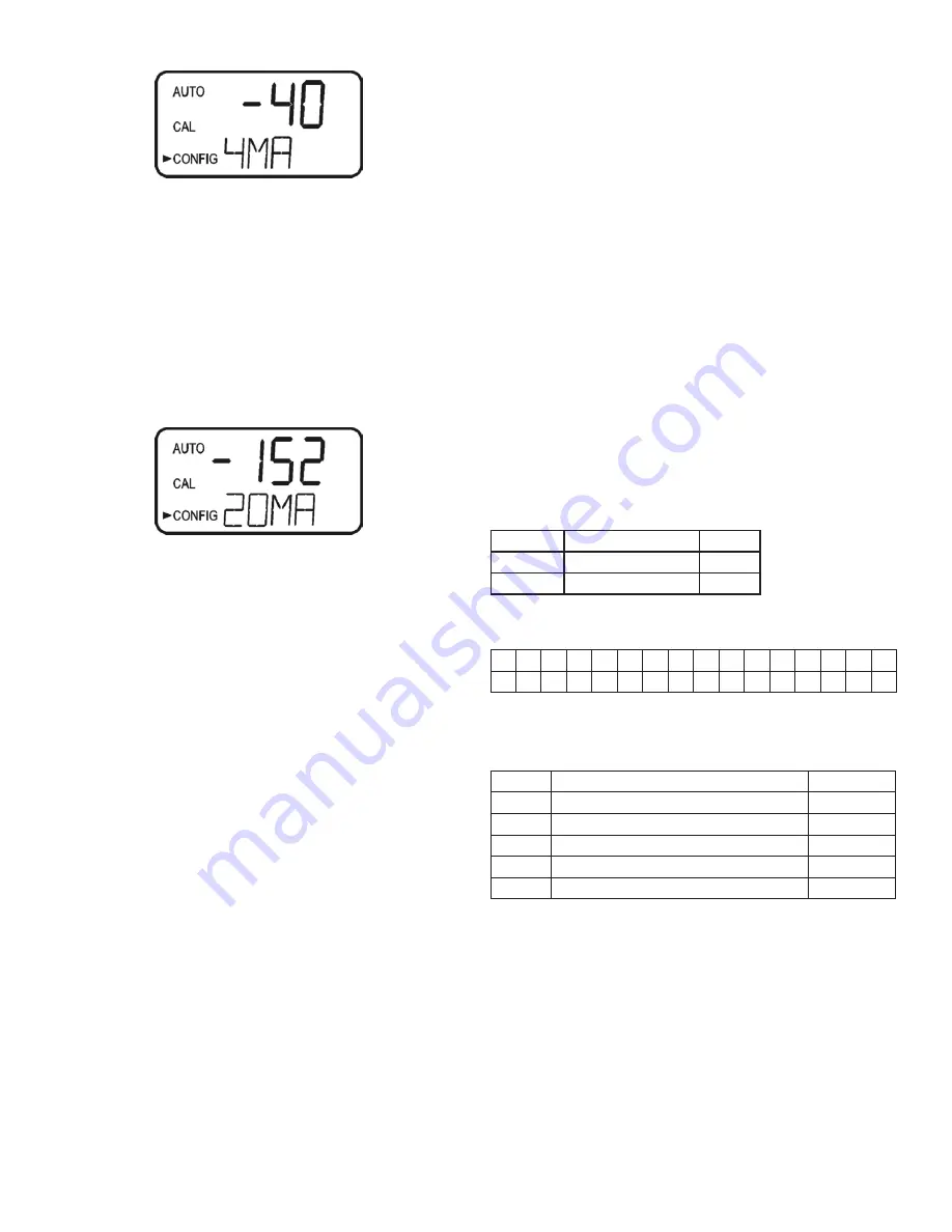
Screen Display - 4mA Adjustment

Содержание HF Scientific AccUView LED Ex

Страница 1: ...Installation Instructions AccUView LED Ex Online UV Analyzer for Hazardous Environments IS HF AccUViewLEDEx 100125 Rev 0 2020 09 ...

Страница 2: ...etting the Error Level 9 Configuring the RS 485 Port 9 Setting the Baud Rate 9 Setting the Address 10 Modbus Mode 10 Security Access Feature 10 Extended Settings 10 Units 10 Speed of Response 10 LCD Backlight Brightness 10 Ultrasonic Cleaning 11 RS 485 Parameter Bits 11 RS 485 Parameter Parity 11 RS 485 Parameter Stop Bits 11 Duty Cycle 11 Desiccant Warning 11 4mA Adjustment 12 20mA Adjustment 12 ...

Страница 3: ...his symbol identifies hazards which if not avoided could result in death or serious injury This symbol identifies hazards which if not avoided could result in minor or moderate injury This symbol identifies practices actions or failure to act which could result in property damage or damage to the equipment This pictorial alerts you to the need to read the manual This pictorial alerts you to electr...

Страница 4: ...s Immunity Tested and passed EN 61326 1 2013 Manufacturer s Name HF scientific inc Manufacturer s Address 16260 Airport Park Drive Suite 140 Fort Myers Florida 33913 Importer s Name Importer s Address Type of Equipment Process Turbidimeter Model AccUView LED Ex 28044 I the undersigned hereby declare that the equipment specified above conforms to the above Directives and Standards Place Fort Myers ...

Страница 5: ... 0 100 0 T 0 2 0 ABS Repeatability 1 0 T 0 002 ABS Resolution 0 1 T 0 0004 ABS Accuracy 2 0 T 0 008 ABS Response Time User selectable from 4 to 60 seconds Path Length 21 5 mm Display Multi Line Liquid Crystal Backlit Display Analog Output Powered loop isolator 4 20 mA 600 Ω drive either 4 20mA or Modbus can be used Communications Port Bi directional RS 485 with Modbus either 4 20mA or Modbus can b...

Страница 6: ...D Ex If inlet pressures can exceed 325 kPa 47 PSI use appropriate tubing to connect to the AccUView LED Ex Electrical Connections All of the electrical connections to the instrument are made at the DIN rail connector The connections are labeled beside the terminal block and are self descriptive Please follow all local and government recommendations and methods for installation of electrical connec...

Страница 7: ...e circuit should be 5A Supply power connections are made ONLY to top MAINS connection on the back of the Air Sentinel III purge controller Terminal 3 Earth Ground Terminal 2 Neutral Terminal 1 Line or Hot Suitable wire would be stranded 3 conductors 18 12 AWG copper or tin plated copper with a voltage rating of 600 VAC with a temperature rating of 90 C or higher Common earth bond points are provid...

Страница 8: ...ating The 4 20 mA is held at this stored reading and will not change until calibration is complete 30 seconds after completion of the calibration the AccUView LED Ex will start taking online measurements These measurements will be averaged with the stored reading depending on setting In order to prevent disruptions in data the operator should release the clamp to allow the sample water to flush ou...

Страница 9: ... has been selected press the button to set it The next prompts will depend on the output selected For RS 485 and Modbus certain combinations of settings are not allowed and some menus will not appear based on previous selections Setting the 4 20 mA If the 4 20 mA output was selected you will be asked to set the 4mA 4MA and 20mA 20MA T or ABS limit levels 1 Select the T or ABS level you wish to ass...

Страница 10: ...turn to the AUTO mode Extended Settings The last few settings are grouped together to prevent them being unintentionally changed To gain access to the extended settings 1 Use the and buttons to select ON 2 Press the button to enter the extended settings menu Units This instrument can measure in either ABS or T This selection affects menus prior to the Extended Settings menu 1 Use the and buttons t...

Страница 11: ...ed press the button to set it RS 485 Parameter Parity There are 3 parity options in this menu Those options are No Parity nOnE odd parity Odd or even parity E the factory default is no parity 1 Use the and buttons to select the desired parity option 2 Once the desired option is selected press the button to set it RS 485 Parameter Stop Bits There are 2 options for this menu 1 stop bit or 2 stop bit...

Страница 12: ...n additional menu in the configuration which gives you the selection of ON or OFF If Low Flow is enabled a flow of less than 150ml minute 04 GPM will cause a screen indication The flow switch can act on the 4 20mA A Low Flow will affect the 4 20mA signal based on the set error level A modbus register is also set The condition takes 2 1 2 minutes of low flow to actuate or restore Screen Display 20m...

Страница 13: ...at Float stored in two consecutive addresses with the first address containing the least significant word lower part of mantissa and the second address containing the most significant word sign exponent and upper part of mantissa Valid Addresses 40001 40XXX Definitions Address Type Register Value Default Function 40001 40002 Float Offset value 0 0 0 0 2 0 40003 Int Decimal places 0 2 XXXXX 1 XXXX ...

Страница 14: ...003 30004 Float Sensor reading raw Sensor reading to six significant places 30005 Int Version major Software version major number 30006 Int Version minor Software version minor number 30007 Int Version revision Software version revision number 30008 Int Model number Product number 30009 Int Model suffix number 0 if no options 30010 Int Reading status 1 Normal 2 Over range 3 Under range 6 Reading p...

Страница 15: ... set point Check air supply Error FLOW Sample flow has stopped Restore flow Error CLN The ultrasonic transducer is not making contact with the spring connections Adjust the cuvette to be sure it is making contact with the springs connections The flow through has been removed Put the flow through back in place For questions or concerns please contact HF scientific Technical Service or Customer Serv...

Страница 16: ...ation lost profits or the cost of repairing or replacing other property which is damaged if this product does not work properly other costs resulting from labor charges delays vandalism negligence fouling caused by foreign material damage from adverse water conditions chemical or any other circumstances over which the Company has no control In addition the Company shall not be responsible for any ...

Отзывы: