Watlow F4T Скачать руководство пользователя страница 4

Watlow F4T Install & Troubleshooting 

1  •

Table of Contents

TC

Table of Contents

Chapter 1: Overview    .  .  .  .  .  .  .  .  .  .  .  .  .  .  .  .  .  .  .  .  .  .  .  .  .  .  .  .  .  .  .  .  .  .  .  .  .2

Available F4T Literature and Resources   .  .  .  .  .  .  .  .  .  .  .  .  .  .  .  .  .  .  .  .  .  .  .  .  . 2

Chapter 2: Install and Wire  .  .  .  .  .  .  .  .  .  .  .  .  .  .  .  .  .  .  .  .  .  .  .  .  .  .  .  .  .  .  .  .  .4

Getting Started Quickly . . .The Logical Approach   .  .  .  .  .  .  .  .  .  .  .  .  .  .  .  .  .  .  . 4
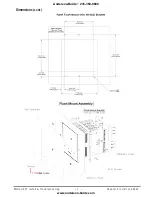
Dimensions  .  .  .  .  .  .  .  .  .  .  .  .  .  .  .  .  .  .  .  .  .  .  .  .  .  .  .  .  .  .  .  .  .  .  .  .  .  .  .  .  .  .  .  .  .  .  . 4
Installing the F4T    .  .  .  .  .  .  .  .  .  .  .  .  .  .  .  .  .  .  .  .  .  .  .  .  .  .  .  .  .  .  .  .  .  .  .  .  .  .  .  .  .  . 5

Panel Mounting the Base  .  .  .  .  .  .  .  .  .  .  .  .  .  .  .  .  .  .  .  .  .  .  .  .  .  .  .  .  .  .  .  .  . 5
Flush Mounting the Base  .  .  .  .  .  .  .  .  .  .  .  .  .  .  .  .  .  .  .  .  .  .  .  .  .  .  .  .  .  .  .  .  . 6

Electrical Isolation    .  .  .  .  .  .  .  .  .  .  .  .  .  .  .  .  .  .  .  .  .  .  .  .  .  .  .  .  .  .  .  .  .  .  .  .  .  .  .  .  . 8
Wiring the F4T Base   .  .  .  .  .  .  .  .  .  .  .  .  .  .  .  .  .  .  .  .  .  .  .  .  .  .  .  .  .  .  .  .  .  .  .  .  .  .  .  . 8
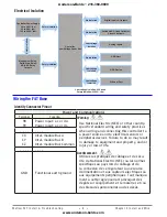
Power Requirements    .  .  .  .  .  .  .  .  .  .  .  .  .  .  .  .  .  .  .  .  .  .  .  .  .  .  .  .  .  .  .  .  .  .  .  .  .  .  . 9

Flex Module (FM) Characteristics   .  .  .  .  .  .  .  .  .  .  .  .  .  .  .  .  .  .  .  .  .  .  .  .  .  . 9

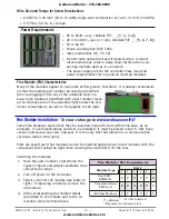
Flex Module Installation   .  .  .  .  .  .  .  .  .  .  .  .  .  .  .  .  .  .  .  .  .  .  .  .  .  .  .  .  .  .  .  .  .  .  .  .  . 9
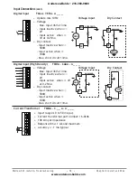
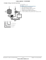
 Wiring the Modules   .  .  .  .  .  .  .  .  .  .  .  .  .  .  .  .  .  .  .  .  .  .  .  .  .  .  .  .  .  .  .  .  .  .  .  .  .  .  . 10

Communications Connections  .  .  .  .  .  .  .  .  .  .  .  .  .  .  .  .  .  .  .  .  .  .  .  .  .  .  .  . 24

Chapter 3: Connecting a PC    .  .  .  .  .  .  .  .  .  .  .  .  .  .  .  .  .  .  .  .  .  .  .  .  .  .  .  .  .  .  .25

Using the User Interface (UI) to Change or View Ethernet Settings   .  .  . 25

Understanding the Front Panel Navigational Buttons    .  .  .  .  .  .  .  .  .  . 25

Connecting the F4T Base to a PC   .  .  .  .  .  .  .  .  .  .  .  .  .  .  .  .  .  .  .  .  .  .  .  .  .  .  .  .  . 27

DHCP Connection   .  .  .  .  .  .  .  .  .  .  .  .  .  .  .  .  .  .  .  .  .  .  .  .  .  .  .  .  .  .  .  .  .  .  .  .  . 27
Fixed IP Connection  .  .  .  .  .  .  .  .  .  .  .  .  .  .  .  .  .  .  .  .  .  .  .  .  .  .  .  .  .  .  .  .  .  .  .  . 27

 Composer Software  .  .  .  .  .  .  .  .  .  .  .  .  .  .  .  .  .  .  .  .  .  .  .  .  .  .  .  .  .  .  .  .  .  .  .  .  .  .  . 28

Starting Composer Software   .  .  .  .  .  .  .  .  .  .  .  .  .  .  .  .  .  .  .  .  .  .  .  .  .  .  .  .  . 28
Verifying Pluggable Flex Module Installation Using Composer   .  .  . 28

Chapter 4: Calibration   .  .  .  .  .  .  .  .  .  .  .  .  .  .  .  .  .  .  .  .  .  .  .  .  .  .  .  .  .  .  .  .  .  .  .30

Calibrating the F4T Inputs    .  .  .  .  .  .  .  .  .  .  .  .  .  .  .  .  .  .  .  .  .  .  .  .  .  .  .  .  .  .  .  .  .  . 30
Required Equipment When Performing Calibration   .  .  .  .  .  .  .  .  .  .  .  .  .  .  . 30
Calibration of Analog Inputs   .  .  .  .  .  .  .  .  .  .  .  .  .  .  .  .  .  .  .  .  .  .  .  .  .  .  .  .  .  .  .  .  . 31
Using Composer Software to Calibrate Analog Inputs   .  .  .  .  .  .  .  .  .  .  .  .  . 32
Using the User Interface to Calibrate Analog Inputs  .  .  .  .  .  .  .  .  .  .  .  .  .  .  . 32

Chapter 5: Troubleshooting  .  .  .  .  .  .  .  .  .  .  .  .  .  .  .  .  .  .  .  .  .  .  .  .  .  .  .  .  .  .  .  .33

Replacing the Battery   .  .  .  .  .  .  .  .  .  .  .  .  .  .  .  .  .  .  .  .  .  .  .  .  .  .  .  .  .  .  .  .  .  .  .  .  .  . 39

Chapter 6: Appendix    .  .  .  .  .  .  .  .  .  .  .  .  .  .  .  .  .  .  .  .  .  .  .  .  .  .  .  .  .  .  .  .  .  .  .  .41

F4T Base Specifications   .  .  .  .  .  .  .  .  .  .  .  .  .  .  .  .  .  .  .  .  .  .  .  .  .  .  .  .  .  .  .  .  .  .  .  . 41

F4T Base Ordering Information   .  .  .  .  .  .  .  .  .  .  .  .  .  .  .  .  .  .  .  .  .  .  .  .  .  .  . 44

Flex Modules and Limit I/O Specifications   .  .  .  .  .  .  .  .  .  .  .  .  .  .  .  .  .  .  .  .  .  . 45

Flex Module - Mixed I/O Ordering Information   .  .  .  .  .  .  .  .  .  .  .  .  .  .  . 48
Flex Module - Limit Ordering Information   .  .  .  .  .  .  .  .  .  .  .  .  .  .  .  .  .  .  . 49

Flex Modules - High Density I/O Specifications   .  .  .  .  .  .  .  .  .  .  .  .  .  .  .  .  .  . 49

Flex Module - High Density Ordering Information  .  .  .  .  .  .  .  .  .  .  .  .  . 53
Flex Module - Communications Ordering Information    .  .  .  .  .  .  .  .  . 53

How to Reach Us   .  .  .  .  .  .  .  .  .  .  .  .  .  .  .  .  .  .  .  .  .  .  .  .  .  .  .  .  .  .  .  .  .  .  .  .  .  .  .  .  . 56

Anderson-Bolds ~ 216-360-9800

www.anderson-bolds.com

Содержание F4T

Страница 1: ...nona Minnesota USA ISO 9001 TOTAL 3Y earWarranty CUSTOMER SATISFACTION F4T Controller Installation and Troubleshooting 1241 Bundy Boulevard Winona Minnesota USA 55987 Phone 1 507 454 5300 Fax 1 507 45...

Страница 2: ...or further infor mation AVERTISSEMENT mise en garde ou danger qui demande plus de pr cisions que l information sur l tiquette de l unit Consultez le manuel de l utilisateur pour plus d informations Un...

Страница 3: ...served 2008 2014 Crank Software Inc All rights reserved Watlow and TRU TUNE are registered trademarks of Watlow Electric Manufacturing Company UL is a registered trademark of Underwriter s Laboratorie...

Страница 4: ...on 27 Fixed IP Connection 27 Composer Software 28 Starting Composer Software 28 Verifying Pluggable Flex Module Installation Using Composer 28 Chapter 4 Calibration 30 Calibrating the F4T Inputs 30 Re...

Страница 5: ...nd your document of choice http www watlow com F4T For the Application Guide click here http www watlow com common catalogs files appguide pdf Your Comments are Appreciated In an effort to continually...

Страница 6: ...when returning any product Make sure the RMA number is on the outside of the carton and on all paperwork returned Ship on a Freight Prepaid basis 3 After we receive your return we will examine it to...

Страница 7: ...hat incoming power is off and connect to the base power supply connector see section Wiring the F4T Base 4 Make note of any I O module slot dependencies installing each one into an appropriate base sl...

Страница 8: ...ur corners of the retention collar assem bly Apply pressure to the face of the control ler while pushing with the screwdriver Don t be afraid to apply enough pressure to properly install the controlle...

Страница 9: ...g panel per supplier recom mendations PEM Standoffs PEM P N S0 632 6 Z1 S0S 632 6 S0A 632 6 S04 632 6 Material Steel Zinc Plated Stainless Steel Aluminum Hardened Stainless Steel 3 Insert the controll...

Страница 10: ...Watlow F4T Install Troubleshooting 7 Chapter 2 Install and Wire Dimensions cont Anderson Bolds 216 360 9800 www anderson bolds com...

Страница 11: ...et aux capteurs lectriques ou aux quipements p riph riques Tout manque ment cette r gle pourrait provoquer des d g ts sur l quipement et le mat riel et ou des blessures personnelles ou des d c s 98 99...

Страница 12: ...ck label as seen in the graphic to the right Flex Module Installation To view video go to www watlow com F4T Some Flex Modules require that they be installed in specific slots within the base As an ex...

Страница 13: ...ed into the wrong slot affix the slot number labels as directed in step 4 above to each module as shown in the graphic below white circle and each removable screw ter minal block Wiring the Modules Pr...

Страница 14: ...led Note Maximum wire size and torque for screw terminations 0 0507 to 3 30 mm2 30 to 12 AWG single wire termination or two 1 31 mm2 16 AWG 0 57 Nm 5 0 lb in torque Input Connections Thermocouple FM M...

Страница 15: ...35 22 16 46 24 26 17 26 41 62 28 66 17 Note 3 wire RTD s self compensate for lead wire resistance up to 10 of wire resistance RTD High Density FMHA RAAA A _ _ _ 2 wire RTD S1 R1 S2 R2 S3 R3 S4 R4 Plat...

Страница 16: ...S3 R3 S4 R4 0 to 20 mA 100 input impedance 0 to 10V dc 20 k input impedance 0 to 50 mV dc 20 M input impedance Scalable Potentiometer FM M L A L U _ _ A A _ _ _ S_ R_ CW CCW Potentiometer 0 to 1 200...

Страница 17: ...rom thermistor manufacturer corresponding to the terms of the Steinhart Hart equation 1 T A Bln R C ln R 3 Thermistor High Density FMHA PAAA A _ _ _ S1 R1 S2 R2 S3 R3 S4 R4 20 M input impedance 0 to 4...

Страница 18: ...ensity FMHA CAAA A _ _ _ Common DC Input B1 D1 D2 D3 D4 D5 D6 Z1 Supply DC Input DC Input DC Input DC Input DC Input Internal Voltage Max input 36V at 3mA Input inactive when 2V Input active when 3V a...

Страница 19: ...pT R 50mA ISC Ip full scale 50mA R T CSI Output N Is Current in secondary of current transformer Ip Current in primary of current transformer T Number of turns through the primary of the transformer R...

Страница 20: ...resistive load only see derating curve 2 000 000 cycle rating for rated load 100 mA minimum load 2 mA maximum off state leakage Do not use on dc loads Output does not supply power Do not drive anothe...

Страница 21: ...2 L4 K4 normally open common normally open common normally open common normally open common Dual Solid State Relays Form A High Density FMHA KAAA A _ _ _ normally open common normally open common norm...

Страница 22: ...on dc loads N O COM N O wiring shared common between each set of outputs See table below for maximum current out put K3 L3 L4 Normally Open Normally Open Common K1 L1 L2 Normally Open Normally Open C...

Страница 23: ..._ _ _ normally open normally closed common L1 K1 J1 5 A at 240V ac or 30V dc maxi mum resistive load Requires a minimum load of 20 mA at 24V 125 VA pilot duty at 120 240V ac 25 VA at 24V ac 100 000 c...

Страница 24: ...t 1 and 2 30 mA dc maximum supply current not to exceed 40 mA combined when both outputs are used Short circuit limited to 50 mA 22 to 32V dc open circuit voltage Use dc and dc to drive exter nal soli...

Страница 25: ...t for all outputs not to exceed 8A Do not connect outputs in parallel Safety Extra Low Voltage Switched DC User selectable voltage 5V dc at 130mA or 19 to 22V dc at 80mA Open Collector Outputs B1 Z1 D...

Страница 26: ...ctor output can sink 1 5 A with the total for all open collector outputs not exceeding 8 amperes Ensure that a kickback diode is reverse wired across the relay coil to prevent damage to the internal t...

Страница 27: ...equired Place a 120 resis tor across T R and T R of last controller on network Do not wire to both the EIA 485 and the EIA 232 pins at the same time Two EIA 485 terminals of T R are provided to assist...

Страница 28: ...mode Auto as shown above Process Value input connected to the PV receiver of the loop function block Set Point which represents the desired value to be maintained by the controller PWR output power le...

Страница 29: ...rent and unique for each controller MAC address is a manufacturer supplied address for the network interface card Display Units F Fahrenheit C Celsius Modbus TCP Enable Yes No Modbus is an industriall...

Страница 30: ...IP changing PC IP address 1 Connect Ethernet cables from F4T RJ45 connector to PC Ethernet port 2 On the PC navigate to the control panel and click on Network and Sharing Center 3 Click on Change adap...

Страница 31: ...then type composer exe in the search box to find the execut able 2 Double click on the file composer exe Note If experiencing difficulties installing or using Composer software prior to contacting Wa...

Страница 32: ...significance The red exclamation will always take prece dence Symbol Description The expected module has been detected No module has been detected in a slot the controller expects to be empty A module...

Страница 33: ...are or while viewing the input from the front panel Operations menu shifts the readings across the entire displayed range by the offset value Use this pa rameter to compensate for sensor error or sens...

Страница 34: ...act on the high and low signals applied in this procedure Note When calibrating a Universal Input configured as a 3 wire RTD ensure that the calibrated source is connected across R and both T and S in...

Страница 35: ...the appropriate Module and Input and then click on Perform Field Calibration 6 Follow instructions on the screen Using the User Interface to Calibrate Analog Inputs To calibrate from the F4T front pa...

Страница 36: ...rip point Set alarm to correct type process deviation or power Set digital input func tion and source instance Alarm won t occur Alarm will not acti vate output Alarm silencing is active Alarm blockin...

Страница 37: ...red or open Incorrect setting of sen sor type Calibration corrupt Correct wiring or re place sensor Match setting to sensor used Check calibration of controller Limit won t clear or reset Limit will n...

Страница 38: ...er to load etc Deactivate Open Loop Detect feature Loop Reversed Error Open Loop Detect is active and the pro cess value is headed in the wrong di rection when the output is activated based on deviati...

Страница 39: ...Closed Loop Set heat cool algorithim to on off or PID Correct output wiring Correct fault in system Set control set point in appropriate control mode and check source of set point remote idle profile...

Страница 40: ...sistor across EIA 485 on last controller Process doesn t con trol to set point Process is unstable or never reaches set point Controller not tuned cor rectly Control mode is incor rectly set Control s...

Страница 41: ...er load wire associated to wrong output Defective current trans former or controller Noisy electrical lines Replace relay Replace relay Route load wire through current transformer from correct output...

Страница 42: ...ifying the battery location 1 Orient the controller as shown in the picture below 2 Notice that the battery compartment is located just below the two USB Removing the old battery 1 Ensure all power is...

Страница 43: ...stic housing 3 Turn and secure the battery so that it sits under the tabs located on the top of the holder 4 Insert the holder into the controller housing with the positive side of the battery ori ent...

Страница 44: ...5 configurations with limit modules AMS 2750 E compliant Analog input process values Tip Maximize field calibration accu racy and uniformity by using advanced F4T features such as Calibration Offset a...

Страница 45: ...tamped Batch Processing with Bar Code Data Entry Via USB Scanner Compatible with many bar code types including Code 128 Code 39 Extended Code 39 Data Matrix Interleaved 2 of 5 ISSN SISAC LOGMARS QR UC...

Страница 46: ...value on load signal Linearization Interpolated or stepped Logic And nand or nor equal not equal latch flip flop Math Average process scale switch over deviation scale differential subtract ratio div...

Страница 47: ...Graphic Trend Charts A None B Graphical trend chart J Data logging K Data logging with encrypted files L Data logging with graphical trend chart M Data logging with encrypted files graphical trend ch...

Страница 48: ...SD at standard conditions Temperature stability 100 PPM C maximum Resolution Input Ranges 0 to 10V 200 V nominal 0 to 20 mA 0 5 mA nominal Potentiometer 0 to 1 200 Inverse scaling Input Type Max Error...

Страница 49: ...range 0 10000 ohms Resistance 20K range 0 20000 ohms Resistance 40K range 0 40000 ohms 1 Thermistor Input Input Type Max Error 25 Deg C Accuracy Range Low Accuracy Range High Units Thermistor 5K range...

Страница 50: ...rrent transformer Watlow part number 16 0246 Switched DC Output Switched dc 22 to 32V dc 30mA per output 40mA per pair option CC Open Collector Output Switched dc open collector 32V dc max 100mA max c...

Страница 51: ...witched dc open collector None CH Switched dc open collector NO ARC 12A power control CC Switched dc open collector Switched dc CJ Switched dc open collector Mechanical relay 5A Form A CK Switched dc...

Страница 52: ...ut None Mechanical relay 5A Form A None YEB Limit control with temperature input None Mechanical relay 5A Form C Single digital input limit reset Flex Modules High Density I O Specifications 4 Univers...

Страница 53: ...eg C F PTII 2 34 0 1343 Deg C RTD 100 ohm 2 00 200 800 Deg C RTD 1000 ohm 2 00 200 800 Deg C mV 0 05 0 50 mV Volts 0 01 0 10 Volts mAdc 0 02 2 20 mAmps DC mAac 5 50 50 mAmps AC Potentiometer 1K range...

Страница 54: ...ird party Thermistor compatibility requirements Base R 25C Alpha Techniques Beta THERM YSI 2 252K Curve A 2 2K3A 004 10K Curve A 10K3A 016 10K Curve C 10K4A 006 3 Universal Process Retransmit Outputs...

Страница 55: ...nt per output 50 VA pilot duty at 120 240 V ac 6 Digital Input Output Option 6 DIO Digital input update rate 10Hz DC voltage Max input 36V 3mA Min high state 3V at 0 25mA Max low state 2V Dry contact...

Страница 56: ...ne Form C J 4 mechanical relay 5A Form A K 2 SSRs 10A L 4 SSRs at 2A each SSRs grouped in 2 pairs with each pair sharing a common Flex Module Communications Ordering Information Part Number Module ID...

Страница 57: ...sions EN 61000 4 2 2009 Electrostatic Discharge Immunity EN 61000 4 3 2010 Radiated Field Immunity EN 61000 4 4 2012 Electrical Fast Transient Burst Immunity EN 61000 4 5 2006 Surge Immunity EN 61000...

Страница 58: ...en installed in a Watlow EZ ZONE CC or F4T Base enclosure that they have useful function Modules were tested as part of these systems for compliance with the following directives 2004 108 EC Electroma...

Страница 59: ...ingdom Email info watlow co uk Website www watlow com From outside The United Kingdom Tel 44 0 115 964 0777 Fax 44 0 115 964 0071 Asia and Pacific Watlow Singapore Pte Ltd 20 Kian Teck Lane 4th Floor...

Отзывы: