


PPC-2000 User’s Guide
Appendix A: Modbus Protocol
Doc.# 30002-00 Rev 2.3
Watlow Anafaze
271
Modbus ASCII and RTU Modes
Modbus protocol specifies two distinct modes: ASCII and RTU.
While the PPC-2000 only supports RTU, it is important to
understand the differences. Typically, ASCII is used for simple
communication tasks or diagnostics while RTU is used where a
more robust and efficient protocol is required.
The mode determines how messages are framed and coded. In
ASCII, each character in a message string is composed of a
hexadecimal character which is correlated to an ASCII
character. So for example, an ASCII message string contains
the value of a process variable, 5500 (550.0 degrees). 5500 in an
ASCII string is composed of 4 bytes, 35 35 30 30. 35 and 30 in
hexadecimal equate to the characters “5” and “0” in the ASCII
table respectively.
In RTU mode, the actual value is embedded in a message
string. There is no translation to ASCII characters. This results
in more compact message strings and efficient serial
communications. The value 5500 in an RTU string is composed
of its hexadecimal equivalent which is only 2 bytes, 15 7C.
Many host devices can communicate in either ASCII or RTU
mode. However, it should be noted that some PLCs can only be
an ASCII host.
Message
Framing
Messages start with a silent interval of at least 3.5 character
times. This is most easily implemented as a multiple of
character times at the baud rate that is being used on the
network (shown as T1-T2-T3-T4 in the figure below). The first
field then transmitted is the device address.
Networked controllers monitor the network bus continuously,
including during the silent intervals. When the first field (the
address field) is received, each device decodes it to find out if it
is the addressed device.
Following the last transmitted character, a similar interval of
at least 3.5 character times marks the end of the message. A
new message can begin after this interval.
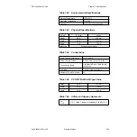
Similarly, if a new message begins earlier than 3.5 character
times following a previous message, the receiving device will
consider it a continuation of the previous message. This will set
an error, as the value in the final CRC field will not be valid for
the combined messages. An example message frame is shown
in
.
Table A.1
Example Message Frame
Start
Address
Function
Data
CRC
Check
End
T1-T2-T3-T4
8 Bits
8 Bits
n X 8 Bits
16 Bits
T1-T2-T3-T4
Содержание Anafaze PPC-2000
Страница 2: ......
Страница 14: ...Table of Contents PPC 2000 User s Guide viii Watlow Anafaze Doc 30002 00 Rev 2 3...
Страница 24: ...List of Tables PPC User s Guide xviii Watlow Anafaze Doc 30002 00 Rev 2 3...
Страница 36: ...Chapter 1 Overview PPC 2000 User s Guide 12 Watlow Anafaze Doc 30002 00 Rev 2 3...
Страница 112: ...Chapter 2 Hardware Installation PPC 2000 User s Guide 88 Watlow Anafaze Doc 30002 00 Rev 2 3...
Страница 184: ...Chapter 4 Troubleshooting PPC 2000 User s Guide 158 Watlow Anafaze Doc 30002 00 Rev 2 3...
Страница 296: ...Chapter 7 Specifications PPC 2000 User s Guide 268 Watlow Anafaze Doc 30002 00 Rev 2 3...
Страница 310: ...Appendix A Modbus Protocol PPC 2000 User s Guide 282 Watlow Anafaze Doc 30002 00 Rev 2 3...
Страница 311: ...Doc 30002 00 Rev 2 3 Watlow Anafaze 283 B Appendix B Declaration of Conformity...
Страница 319: ...PPC 2000 User s Guide Glossary Doc 30002 00 Rev 2 3 Watlow Anafaze 291...
Страница 320: ...Glossary PPC 2000 User s Guide 292 Watlow Anafaze Doc 30002 00 Rev 2 3...