background image

9

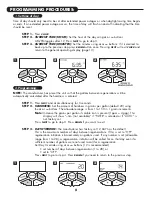
STEP 4

– 

REGENERATION HOUR:

The manufacturer has factory set 2:00 A.M. as the default. This

is the hour of day for regeneration and can be reset by using 

+

or 

buttons. “AM/PM”

toggles after 12. The default time is 2:00 a.m. (recommended for a normal household).

Press 

NEXT

to go to step 5. Press 

REGEN

if you need to return to the previous step.

STEP 5

– 

REGENERATION MINUTES:

Set the minutes using 

+

or 

buttons. Press 

NEXT

to exit 

installer programming. Press 

REGEN

if you need to return to the previous step. To initiate 

an immediate manual regeneration, press and hold the 

REGEN

button for three seconds. 

The system will begin to regenerate immediately. The control may be manually stepped
through the regeneration cycles by pressing 

REGEN

.

2. Programming cont’d:

4

5

GENERAL OPERATION DISPLAYS

REGENERATION 

MODE

OPERATING DISPLAYS AND INSTRUCTIONS:

1. 

GENERAL OPERATION:

When the system is operating,

one of three displays may be shown. Pressing 

NEXT

will

alternate between the displays. One of the displays is
always the current time of day. The second display shows
the current treated water flow rate through the system in
Gallons Per Minute. The third display is one of the
following: days remaining or volume remaining. Days
remaining is the number of days left before the system
goes through a regeneration cycle. Capacity remaining is
the gallons that will be treated before the system goes
through a regeneration cycle. The user can scroll between
the displays as desired. 

If a water meter is installed, the word “Softening” or
“Filtering” flashes on the display when water is being
treated (i.e. water is flowing through the system).

2. 

REGENERATION MODE:

Typically a system is set to regenerate 

at a time of no water use. If there is a demand for water when the
system is regenerating, untreated water will be delivered. When 
the system begins to regenerate, the display will change to include
information about the step of the regeneration process and the time
remaining for that step to be completed. The system runs through the
steps automatically and will reset itself to provide treated water when
the regeneration has been completed.

Содержание CSP-844

Страница 1: ...CareSoft Pro Series Metered Water Softeners For Models CSP 844 CSP 948 CSP 1044 CSP 1054 CSP 1248 CSP 1354 For Cabinet Models CSPC 835 CSPC 935 CSPC 1035 ...

Страница 2: ...o come when installed and operated properly Please study this manual carefully and understand the cautions and notes before installing This manual should be kept for future reference If you have any questions regarding your water conditioner contact your local dealer or WaterCare at the following WaterCare 1900 Prospect Court Appleton WI 54914 Phone 920 682 6823 Fax 920 682 7673 YOUR WATER TEST Ha...

Страница 3: ...uickly exit any Programming Installer Settings etc press CLOCK Any changes made prior to the exit are incorporated If desired two regenerations within 24 hours are possible with a return to the preset program To do a double regeneration 1 Press the REGEN button once REGEN TODAY will flash on the display 2 Press and hold the REGEN button for five seconds until a regeneration begins Once the valve h...

Страница 4: ... to the building while not allowing water to exit from the system to the building Fig 3 This allows the service technician to draw brine and perform other tests without the test water going to the building NOTE The system must be rinsed before returning the bypass valve to the normal position 4 SHUT OFF POSITION The inlet handle points to the center of the bypass valve and the outlet handle points...

Страница 5: ... to be unscrewed or tightened by hand or with the special plastic Service Wrench CV3193 01 If necessary pliers can be used to unscrew the nut or cap Do not use a pipe wrench to tighten nuts or caps Do not place screwdriver in slots on caps and or tap with a hammer SITE REQUIREMENTS water pressure 30 100 psi current draw is 0 5 amperes water temperature 33 100 F 0 5 37 7 C the plug in transformer i...

Страница 6: ...clamp or jumper wiring NOTE If replacing an existing softener also replace the ground clamps wire If removing a softener replace the piping with the same type of piping as the original to assure plumbing integrity and grounding 7 DRAIN LINE First be sure that the drain can handle the backwash rate of the system Solder joints near the drain must be done prior to connecting the drain line flow contr...

Страница 7: ...uilding structure Your softener is equipped with a brine tank safety float which greatly reduces the chance of an accidental brine overflow In the event of a malfunction however an overflow line connection will direct the overflow to the drain instead of spilling on the floor where it could cause considerable damage This fitting is an elbow on the side of the brine tank Attach a length of 1 2 I D ...

Страница 8: ...SS Set the amount of hardness in grains per gallon default 20 using the or buttons The allowable range is from 1 to 150 in 1 grain increments Note Increase the grains per gallon if soluble iron is present 1ppm 4 gpg This display will show nA not available if FILTER is selected or if AUTO is not factory set Press NEXT to go to step 3 Press REGEN if you want to exit STEP 3 DAY OVERRIDE The manufactu...

Страница 9: ...e displays One of the displays is always the current time of day The second display shows the current treated water flow rate through the system in Gallons Per Minute The third display is one of the following days remaining or volume remaining Days remaining is the number of days left before the system goes through a regeneration cycle Capacity remaining is the gallons that will be treated before ...

Страница 10: ... thereafter see Start Up Instructions for regeneration sequence the water softener will deliver water but it will be untreated IMPORTANT With the Dry Salt Storage Feature the brine tank will refill 4 hours before the actual regeneration occurs You may experience a small amount of noise for a short period of time at 10 00 p m with typical setting on the night that regeneration is to occur This nois...

Страница 11: ...ter softener include a dry salt storage feature no water in brine tank between regeneration the manufacturer recommends the use of solar salt for best results The brine tank is manufactured for the use of solar pellets or rock salt If pellet or rock salt is used a cleaning of the brine tank every six months is recommended If the dry salt storage feature is not being utilized block salt may be used...

Страница 12: ... up it could result in a salty water complaint after the first regeneration During the first regeneration the unit will draw out the initial volume of brine regenerant and refill it with the correct preset amount 2 With the softener in bypass mode press and hold the REGEN button until the motor starts Release button The display reads FILL and the remaining time in this step is counting down Since ...

Страница 13: ... any remaining debris and air from the system again 1 Full open a cold water faucet preferably at a laundry sink or bathtub without an aerator 2 Wait two to three minutes or until water runs clear then turn water off 3 Turn on hot water and check for air then turn water off after air is discharged 8 SANITIZING OF UNIT UPON INSTALLATION AND AFTER SERVICE At this time it is advised to sanitize the s...

Страница 14: ...C remove meter and check for debris D defective meter D replace meter E defective PC board E replace PC board Unit regenerates at wrong time of day A past power outage A reset time of day B incorrect time of day displayed B reset time of day C time of regenerant set incorrectly C reset time of regeneration D control set at on 0 D check with regeneration time option in programming E control set at ...

Страница 15: ...0 circuit board failure _______________ TWIN ALT SYSTEMS Error code 1006 motor ran too long Error code 1007 unexpected stall A valve has just been serviced 1001 A press NEXT and REGEN for 5 seconds or momentarily unplug power source from PC board B motor gears not fully engaged motor wires broken failed motor 1001 B check motor wiring C foreign material stuck in valve 1002 C check piston and space...

Страница 16: ...3837 01 CareSoft Pro cover 1 2 CV3107 1 Motor 1 3 CV3106 1 Drive bracket spring clip 1 4 CV3851WN PC board 1 5 CV3110 Drive gear 12 x 36 3 6 CV3109 Drive gear cover 1 7 CV3002CC Drive assembly CV3186 Transformer 110V 12V 1 CV3543 Optional weather cover 1 NOTE Battery Location 4 1 2 3 5 6 7 ...

Страница 17: ...iston assembly upflow 1 CV3407 1 25 piston assembly downflow 1 5 CV3174 Regenerant piston 1 6 CV3180 O ring 337 1 7 CV3105 O ring 215 1 8 CV3556 Screw 1 4 20x1 1 2 18 8SS 1 9 CCI 00318337 Nut 1 4 20 HEX 18 8SS 1 10 CV3016 QC2 clamp assembly includes screw nut 1 11 CV3452 O ring 230 1 12 CV3015 WS1 QC2 Tank adapter assembly includes O rings 1 13 CV3001 1 body assembly downflow 1 CV3001UP 1 body ass...

Страница 18: ...ion Qty 1 CV3151 Nut 1 quick connect 2 2 CV3150 Split ring 2 3 CV3105 O ring 215 2 4 CV3145 Bypass rotor 1 2 5 CV3146 Bypass cap 2 6 CV3147 Bypass handle 2 7 CV3148 Bypass rotor seal retainer 2 8 CV3152 O ring 135 2 9 CV3155 O ring 112 2 10 CV3156 O ring 214 2 ...

Страница 19: ...y BLUE CV3010 1G G injector assembly YELLOW CV3010 1H H injector assembly GREEN CV3010 1I I injector assembly ORANGE CV3010 1J J injector assembly LIGHT BLUE CV3010 1K K injector assembly LIGHT GREEN not shown CV3170 O ring 011 lower not shown CV3171 O ring 013 upper The injector plug and the injector each use one lower and one upper o ring BRINE ELBOW ASSEMBLY Item No Part No Description Qty 1 CV...

Страница 20: ... 1 0 DLFC for 3 4 elbow CV3162 013 1 3 DLFC for 3 4 elbow CV3162 017 1 7 DLFC for 3 4 elbow CV3162 022 2 2 DLFC for 3 4 elbow CV3162 027 2 7 DLFC for 3 4 elbow CV3162 032 3 2 DLFC for 3 4 elbow CV3162 042 4 2 DLFC for 3 4 elbow CV3162 053 5 3 DLFC for 3 4 elbow 8 CV3331 Drain elbow and retainer assembly Items 2 and 3 nut and insert are only used with 1 2 I D by 5 8 O D polytubing For other piping ...

Страница 21: ...18 01 Turbine assembly 1 4 CV3105 O ring 215 1 5 CV3003 01 Meter plug assembly 1 6 CV3013 Optional mixing valve 1 REPLACEMENT PARTS Although no tools are necessary to assemble or disassemble the valve the Service Wrench shown in various positions on the valve is available to aid in assembly or disassembly SERVICE WRENCH CV3193 01 ...

Страница 22: ...t grid support 6 needed WC 1 CH1088 Optional Salt grid handle WC 1 CH1072 01 Optional 18 diameter salt grid 1 CH1080 Optional 24 diameter salt grid 1 3 CG21833CB1C00 18 x 33 brine tank black 1 CG21840CB1C00 18 x 40 brine tank black 1 CG22441CB1C00 24 x 41 brine tank black 1 4 CH1030 27 4 x 27 brine well 18 x 33 BT 1 CH1030 34 5 4 x 34 5 brine well 18 x 40 24 x 40 BT s 1 5 CH1018 2 piece overflow s...

Страница 23: ...tion Qty 1 CG2197 01 Salt and tank cover must be ordered together 1 2 CG2724HP 01 Windsor cabinet white with black lids 1 3 CH1090 01 Optional salt grid for 8 diameter tank and 4 brine well 1 CH1090 02 Optional salt grid for 9 diameter tank and 4 brine well 1 CH1090 03 Optional salt grid for 10 diameter tank and 4 brine well 1 ...

Страница 24: ...2 1 brass sweat assembly 2 1 CV3151 Nut 1 quick connect 2 2 CV3150 Split ring 2 3 CV3105 O ring 215 2 4 CV3188 Fitting 2 3 4 BRASS SWEAT Item No Part No Description Qty CV3007 03 3 4 brass sweat assembly 2 1 CV3151 Nut 1 quick connect 2 2 CV3150 Split ring 2 3 CV3105 O ring 215 2 4 CV3188 01 Fitting 2 1 PLASTIC MALE NPT Item No Part No Description Qty CV3007 04 1 plastic male NPT assembly 2 1 CV31...

Страница 25: ...V3375 Fitting 2 3 4 JOHN GUEST ELBOW Item No Part No Description Qty CV3007 15 3 4 John Guest elbow assembly 2 1 CV3151 Nut 1 quick connect 2 2 CV3150 Split ring 2 3 CV3105 O ring 215 2 4 CV3790 Fitting 2 1 BRASS SHARK BITE Item No Part No Description Qty CV3007 13 1 brass Shark Bite assembly 2 1 CV3151 Nut 1 quick connect 2 2 CV3150 Split ring 2 3 CV3105 O ring 215 2 4 CV3629 Fitting 2 3 4 BRASS ...

Страница 26: ...Max Service PSI 8 6 14 1 15 0 Min to Max Working Pressure PSI 30 100 30 100 30 100 Min to Max Operating Temperature ºF 33 100 33 100 33 100 Max Flow to Drain During Regeneration GPM 1 3 1 7 2 2 Amount of High Capacity Cat ion Resin Cu Ft 50 75 1 0 Electrical Requirements volts hertz 110 50 60 110 50 60 110 50 60 Pipe Size 1 1 1 Total Dimensions Media Tank 13 5 W x 42 5 H x 13 5 W x 42 5 H x 13 5 W...

Страница 27: ...mponent at its expense and return part freight collect The above provisions of the warranty are valid as long as the unit is connected in compliance with local plumbing codes and in an equivalent manner and condition of the original installation and is owned by the original owner This warranty does not cover damages due to accident fire flood freezing or any other Act of God We are not responsible...

Страница 28: ...e steps as shown to the right Access this mode by pressing NEXT and button simultaneously NOTE Hardness display shows nA if used as a filter If other displays do not appear refer to manual QUICK REFERENCE GUIDE GENERAL OPERATION When the system is operating one of three displays will be shown time of day gallons of treated water available or gallons per minute Pressing NEXT will toggle between the...

Отзывы: