Hardware Guide
5
Hardware Specifications
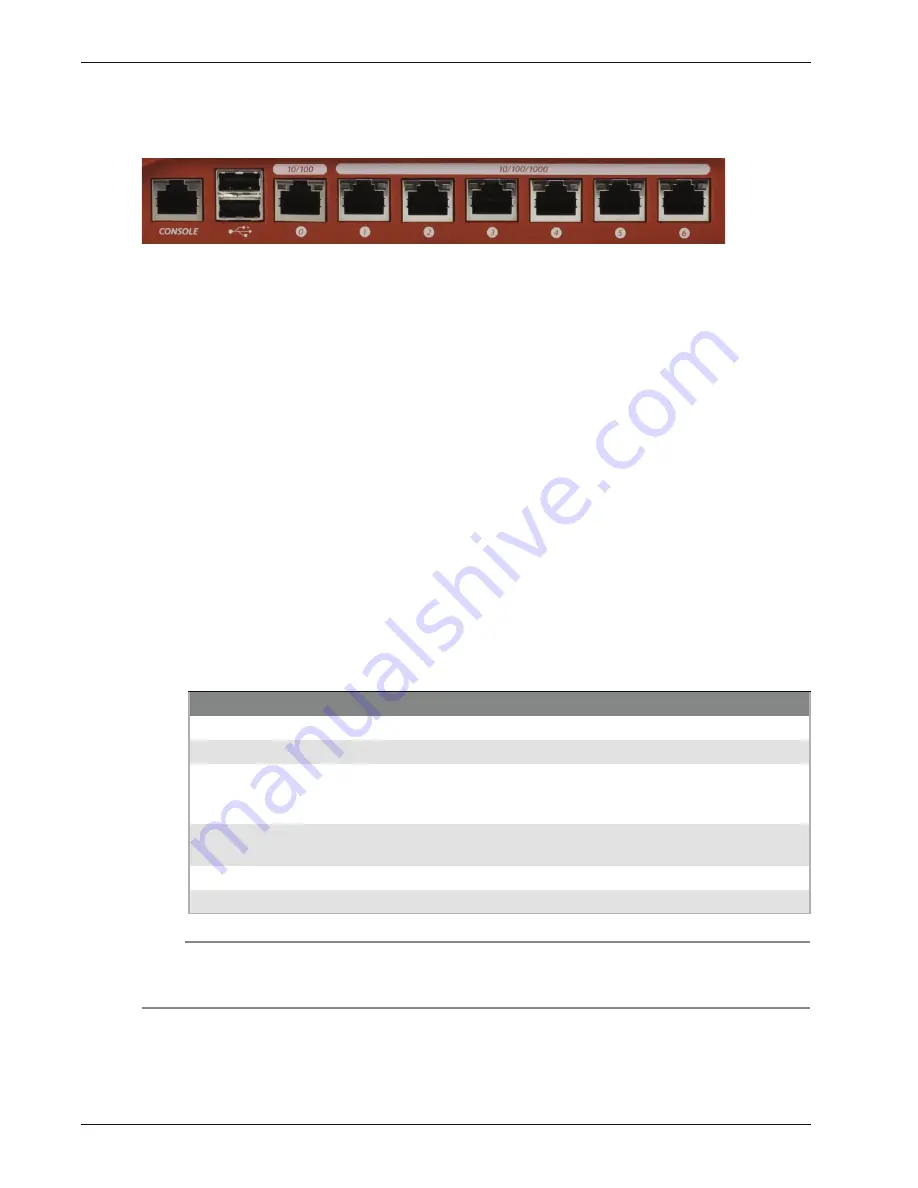
All interfaces are on the front of the device.
Serial port (Console)
An RJ45 connector for the serial interface.
Dual USB interface
The two USB interfaces are reserved for future use.
Network Interfaces
The interfaces have standard RJ45 connectors and are labeled 0,1,2,3,4,5,6.
Interface 0 — supports link speeds of 10 or 100 Mbps.
Interfaces 1 - 6 — support link speeds of 10, 100, or 1000 Mbps.
Interface 0 does not support Auto-MDIX, which automatically senses the cable polarity. Use these
guidelines to decide which type of Ethernet cable to use with Interface 0.
To connect Interface 0 to an interface on a switch or router that supports Auto-MDIX, you can
use either Ethernet cable.
To connect Interface 0 to ain interface on an older switch or router that does not support Auto-
MDIX, use the green Ethernet cable. Your switch or router might be set to a different polarity. If
the green Ethernet cable does not work, try the red cross-over Ethernet cable.
To connect Interface 0 to a PC, use the red cross-over Ethernet cable.
Indicators for network interfaces
At the top of each labeled network interface, there is a pair of indicators. The indicator at the left of
the interface is the activity indicator for that interface. The indicator at the right shows the connection
speed for that interface.
Note
When the device is powered off, but the AC power is plugged in, the Link and Activity indicators for
interface 0 continue to operate, but the interface does not pass traffic. All other network interface
indicators are inactive.
Indicator
Indicator color
Interface Status
Activity (upper left)
Yellow
Power on, connection established
Not lit
Power off, no connections
Blinks
(speed of blink increases as the
data flow increases)
Data sent and received
Connection Speed
(upper right)
Not lit
Link speed: 10 Mbps
Green
Link speed: 100 Mbps
Yellow
Link speed: 1000 Mbps


