WGSMSC Quick Start Guide
2
1. Using the WGSMSC as an SMS Communicator
1.1 Usage Overview
1.2 Installation Requirements
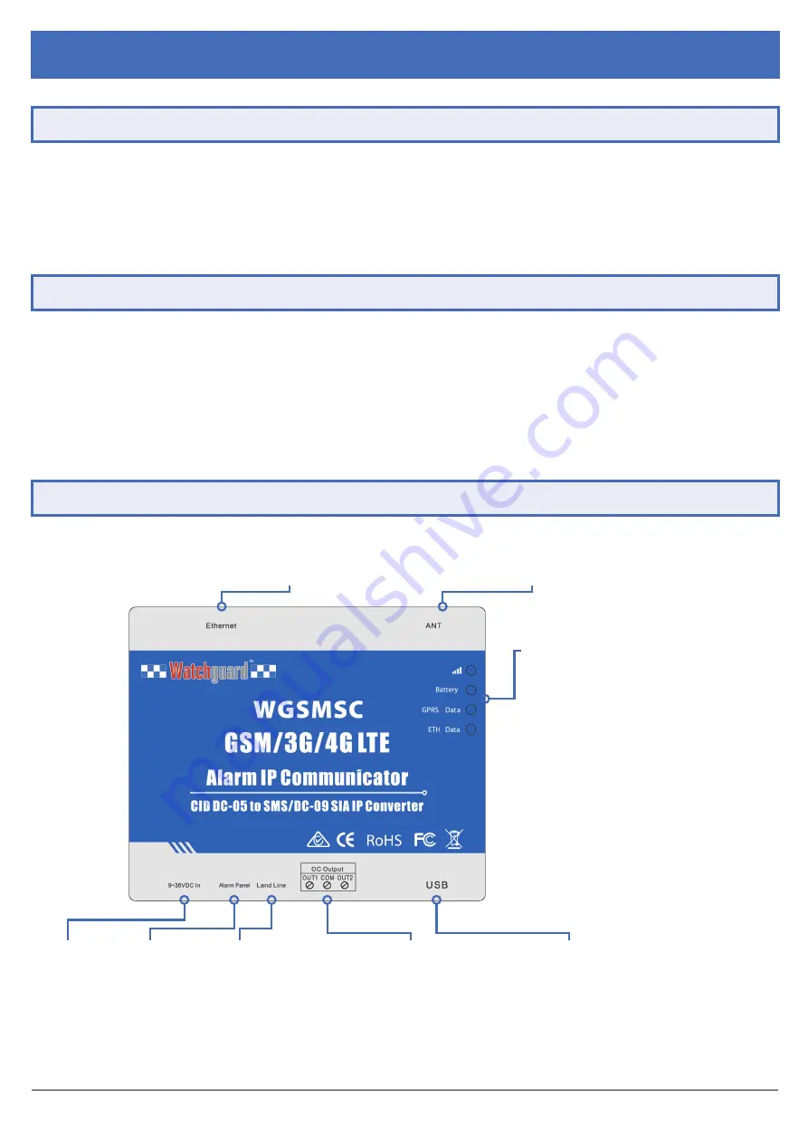
1.3 Product Diagram
9~36VDC In:
Power input
Alarm Panel:
Alarm panel
connection
Land Line:
Land line
connection
OC Output:
OUT1
- 1st output, OC type
COM
- General terminal
OUT2
- 2nd output, OC type
USB Port:
Connect to PC for configuration
Indicator Lights:
1.
SMS Signal
Blinking every 0.5s
- Registering network
Blinking every 1.0s
- Normal signal
2.
Power Supply
Blinking every 1.0s
- Battery charging
On
- Battery fully charged
Off
- No power from battery or adapter
3.
GPRS Data
Blinking every 1.0s
- Transferring GPRS data
4.
Ethernet
Blinking
- Transferring GPRS data
On
- Connected to server
ANT:
Included antenna connects here
Ethernet:
Network cable connection
Before installation, ensure the following are accounted for:
•
One installed and active alarm panel (Watchguard™ WGAP864 recommended)
•
One PC / laptop for communicator configuration via USB
•
One active SIM card for SMS communication
•
Mobile network connection
This section covers how to set up the WGSMSC for use as an SMS alarm communicator. In this configuration, the communicator
can notify up to 5 users via SMS for events such as alarm activation and power loss. This turns your alarm into a self monitored
alarm system that can be used inline with your monitoring service.
In this section, learn how to connect and configure your communicator via PC, set up which mobile numbers the communicator
contacts, alarm events and messages sent in response and how to connect the communicator to the alarm panel.
Fig. 1.3.1:
WGSMSC diagram & connections


