6
Cabling the Firebox® X
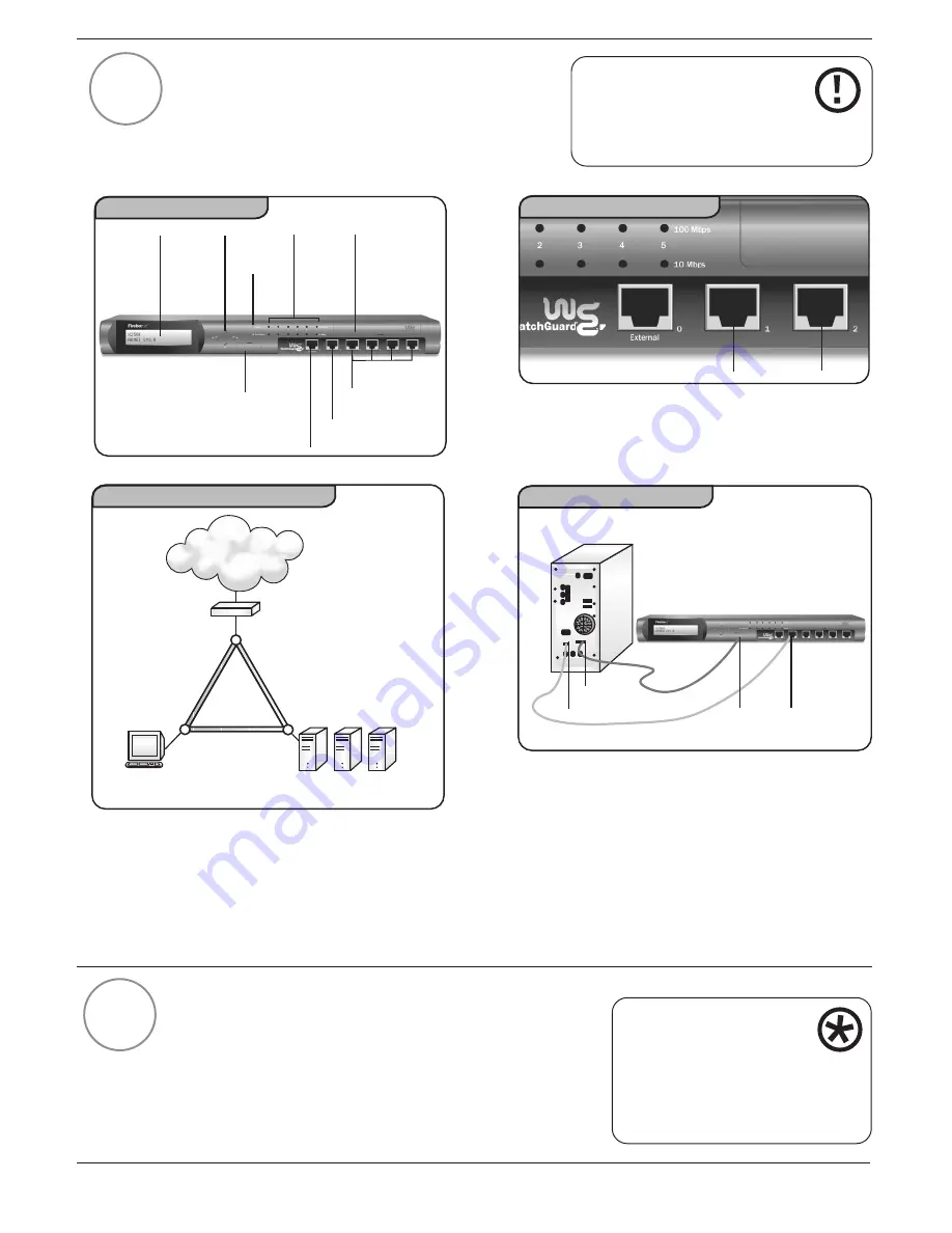
Cable the Firebox X to your management station as
follows. (Refer to Figures 4, 5, 6 and 7 below.) Note:
All Firebox ports are NIC ports, not hub ports. Refer
to Figure 5 for details on unmarked ports.
Running the QuickSetup Wizard
After you finish setting up the Management Station and
cabling the Firebox X, use the QuickSetup Wizard to
create a basic configuration file. This enables the
Firebox X to function as a simple but immediately
effective firewall.
4
IMPORTANT
To set up the Firebox X using
TCP/IP, see the Getting Started
section of the User Guide.
Optional
Interfaces
Console
Power
Light
Network
Port
lights
Trusted
Interface
External
Interface
LCD
Display
Removable
Hard Drive Slot
Figure 4
Scrolling
Buttons
Firebox X Front Panel
Trusted
Optional
Location of trusted ports
Figure 5
Router (optional)
HTTP
Server
Management
SMTP
Server
FTP
Server
External
Trusted
Optional
Internet
Network Configuration Diagram
Figure 6
Management Station PC
(back)
Trusted
Figure 7
Firebox X (front)
Cabling for Provisioning
COM Port
Ethernet Port
Console
5
■
Only the external port is labeled on the
Firebox X. Please review highlighted areas for
the trusted ports.
■
Plug the power cord into the Firebox power
input and into a power source. Leave the
power switch ‘off’ until the end of step 6.
■
Use the blue serial cable to connect the
Firebox Serial Port (CONSOLE) to the
management station COM port.
Use the red crossover cable to connect the
Firebox trusted interface to the management
station Ethernet port. (You can disconnect
your Internet connection if necessary.)
To test your connection to
the Firebox through the
Management Software before
deploying the Firebox on your
network, see the Getting Started
section of the User Guide.


