background image

18

4

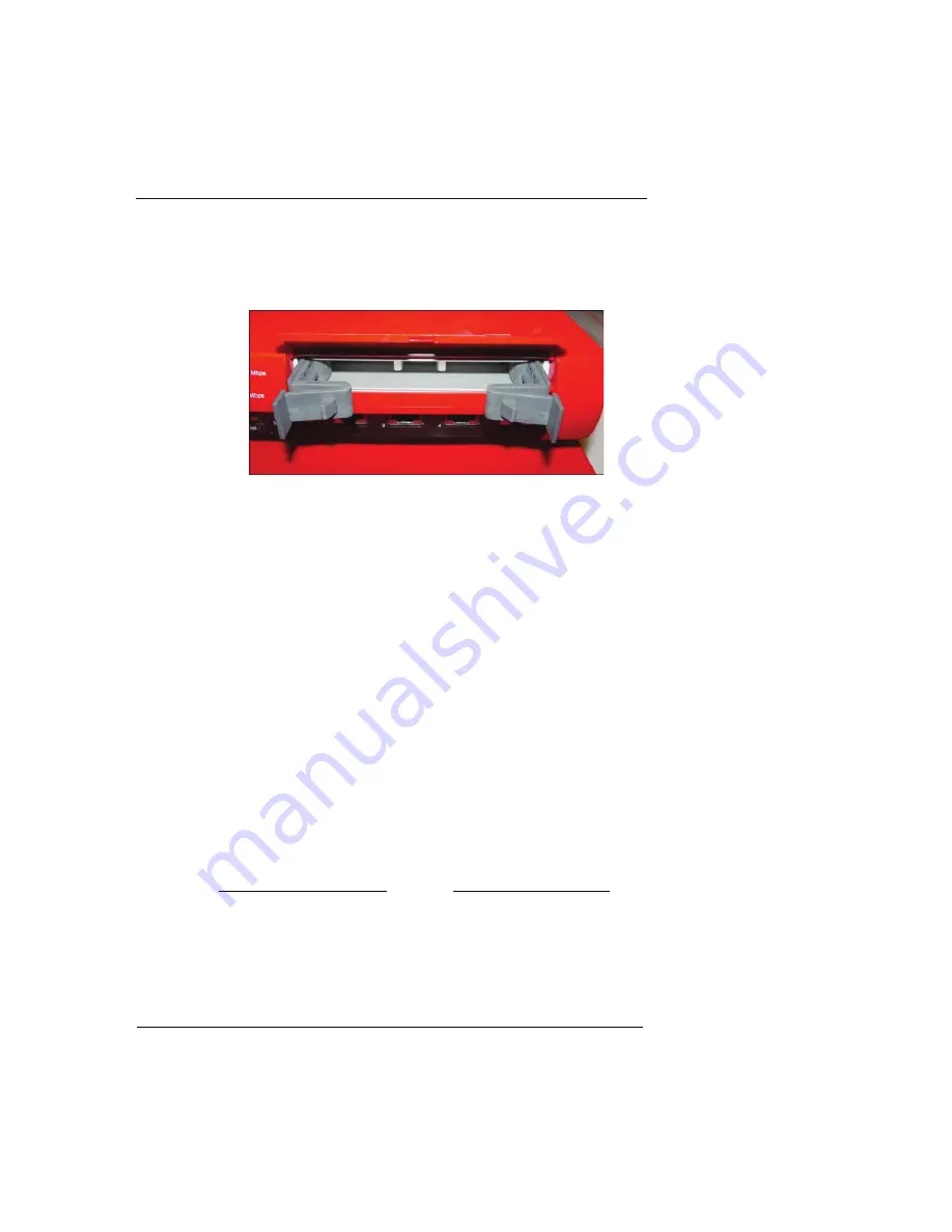
With your thumbs, press the two tabs in the center of the 
hard drive tray outward slightly to release the tray arms. Pull 
the arms gently until they are fully open.

5

Remove the tray by pulling on the arms until the tray slides 
out of the Firebox. Keep the tray in a safe place. If you ever 
remove the hard drive from your Firebox, you must replace 
the original tray at that time.

6

Remove the new hard drive from its packaging. Prepare it 
for installation by using your thumbs to press the two tabs 
in the center slightly outward to release the tray arms. Pull 
the arms gently until they are fully open.

7

Insert the hard drive tray into the hard drive slot on the 
front of the Firebox. Using the tray arms, push the tray in 
until the tray is fully seated.

If you have trouble pushing the hard drive in, move it slightly from 
side to side while applying firm inward pressure.

8

Push the tray arms toward the center and push gently on 
the two tabs until they click to lock the arms into place. 

If the two tabs do not click, the tray is not fully inserted into the 
Firebox. Extend the tray arms and push the tray in further.

9

Close the door.

If the door does not close completely, the tray is not fully inserted 
into the Firebox. Extend the tray arms and push the tray in further.

N

OTE

The hard drive tray must be fully inserted into the Firebox 
before you turn the Firebox power on. The hard drive tray is 
installed correctly if:
    *the hard drive tray arms swing in completely and the two 
tabs click into place; and

Содержание Firebox SSL Core

Страница 1: ...Firebox SSL Core Hardware Guide Firebox SSL VPN Gateway ...

Страница 2: ... is licensed pursuant to a separate end user license agreement and warranty the Product BY USING THE PRODUCT YOU either an individual or a single entity AGREE TO THE TERMS HEREOF If you do not agree to these terms please return this package along with proof of purchase to the authorized dealer from which you purchased it for a full refund WatchGuard Technologies Inc WatchGuard and you agree as set...

Страница 3: ...WARRANTY OF UNINTERRUPTED OR ERROR FREE OPERATION ANY OBLIGATION LIABILITY RIGHT CLAIM OR REMEDY IN TORT WHETHER OR NOT ARISING FROM THE NEGLIGENCE WHETHER ACTIVE PASSIVE OR IMPUTED OR FAULT OF WATCHGUARD OR FROM PRODUCT LIABILITY STRICT LIABILITY OR OTHER THEORY AND ANY OBLIGATION LIABILITY RIGHT CLAIM OR REMEDY FOR LOSS OR DAMAGE TO OR CAUSED BY OR CONTRIBUTED TO BY THE PRODUCT 4 LIMITATION AND ...

Страница 4: ...S BEING USED BY AN ENTITY THE INDIVIDUAL INDICATING AGREEMENT TO THESE TERMS BY USING THE PRODUCT REPRESENTS AND WARRANTS THAT A SUCH INDIVIDUAL IS DULY AUTHORIZED TO ACCEPT THE WARRANTY ON BEHALF OF THE ENTITY AND TO BIND THE ENTITY TO THE TERMS OF THIS WARRANTY B THE ENTITY HAS THE FULL POWER CORPORATE OR OTHERWISE TO ENTER INTO THE WARRANTY AND PERFORM ITS OBLIGATIONS UNDER THE WARRANTY AND C T...

Страница 5: ...Declaration of Conformity Firebox SSL Core Hardware Guide 5 Declaration of Conformity ...

Страница 6: ...interference that may cause undesired operation CE Notice The CE symbol on your WatchGuard Technologies equipment indicates that it is in compliance with the Electromagnetic Compatibility EMC directive and the Low Voltage Directive LVD of the European Union EU Industry Canada This Class A digital apparatus meets all requirements of the Canadian Inter ference Causing Equipment Regulations Cet appar...

Страница 7: ...NT TYPE REC OMMENDED BY THE MANUFACTURER DISPOSE OF USED BATTERIES ACCORDING TO THE MANUFACTURER S INSTRUCTIONS ATTENTION IL Y A DANGER D EXPLOSION S IL Y A REMPLACEMENT INCORRECT DE LA BATTERIE REMPLACER UNIQUEMENT AVEC UNE BAT TERIE DU MÊME TYPE OU D UN TYPE ÉQUIVALENT RECOMMANDÉ PAR LE CONSTRUCTEUR METTRE AU REBUT LES BATTERIES USAGÉES CON FORMÉMENT AUX INSTRUCTIONS DU FABRICANT ...

Страница 8: ...8 ...

Страница 9: ... 5 FCC Certification 6 CE Notice 6 Industry Canada 6 VCCI Notice Class A ITE 7 Package Contents 11 Hardware Specifications 12 Environmental Requirements 12 Hardware Description 13 Firebox SSL Core front panel 13 Firebox SSL Core rear view 16 Installing the Hard Drive 16 Removing the Hard Drive 19 ...

Страница 10: ...10 ...

Страница 11: ...n For information on installing the Firebox SSL Core device see the Firebox SSL QuickStart Guide Thank you for selecting the Firebox SSL Core to provide SSL VPN capabilities for your users We look forward to meeting your security requirements in these dynamic times Package Contents The package should contain the following Firebox SSL Core device Firebox SSL QuickStart Guide 3 straight through Ethe...

Страница 12: ...cific hardware specifications for the Firebox SSL Core Environmental Requirements WatchGuard recommends physically installing a Firebox SSL Core device under the following conditions Processor 1 2 GHz Intel Based Processor Memory Flash 64 Mbyte Memory RAM 256 Mbyte Network interfaces 6x10 100 Serial ports 1 DB9 Power supply 100 240 VAC Autosensing Dimensions D 9 5 W 16 75 H 1 75 Weight 9 2 lbs wit...

Страница 13: ...r environmental requirements Hardware Description Firebox SSL Core front panel The following photograph shows the entire front view Operating temperature 0 40 degrees Celsius 32 104 degrees Fahrenheit Operating humidity 10 85 Non operating temperature 40 70 degrees Celsius Non operating humidity 10 95 Non condensing at 55 degrees Celsius 131 degrees Fahrenheit Non operating random vibration 7 28 H...

Страница 14: ...nformation Use the buttons to change the information that appears LCD Console Buttons LCD buttons are used to view information on the Firebox SSL See the Firebox SSL VPN Gateway Administration Guide for more information Power A yellow LED light emitting diode indicates that the power is on Arm Disarm The Arm Disarm LED lights green when the device is working and red when it is not working ...

Страница 15: ...0 1 2 3 4 and 5 Each port has a corresponding LED located above the interface ports Interface ports 2 3 4 and 5 are inactive LED The six pairs of LEDs are labeled 0 1 2 3 4 and 5 and they correspond to the interface ports below The LEDs show the link and connection speed of the interface When the interface runs at 100 Mbit the top LED is green When the interface runs at 10 Mbit the bottom LED is g...

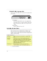
Страница 16: ...ller invoice for the hard drive upgrade You must supply this proof of purchase to WatchGuard with any warranty claims 1 Turn off the Firebox System Requirement Hardware The hard drive will only operate on a Firebox SSL Core Appliance Software The Firebox must have an approved version of appliance software installed For Firebox SSL Core the appliance software is included on the hard drive To make s...

Страница 17: ... not a hot swap device Failure to turn the Firebox off before installing the hard drive can result in damage to the hard drive 2 On the front right side of the Firebox look for the door covering the hard drive slot 3 Lift the door and find the two release tabs for the hard drive tray ...

Страница 18: ...ve slot on the front of the Firebox Using the tray arms push the tray in until the tray is fully seated If you have trouble pushing the hard drive in move it slightly from side to side while applying firm inward pressure 8 Push the tray arms toward the center and push gently on the two tabs until they click to lock the arms into place If the two tabs do not click the tray is not fully inserted int...

Страница 19: ...ed Removing the Hard Drive You can remove a hard drive from a Firebox X or move a hard drive from one Firebox to another Before you remove or add a hard drive you must turn the Firebox off The hard drive is not a hot swap device If you move a hard drive to a different Firebox the Firebox will automatically reformat the hard drive if neces sary NOTE If you have trouble removing a hard drive from a ...

Страница 20: ...20 ...
Отзывы: