ELECTRICAL CONNECTIONS
All electrical connections must be made in accordance with local wiring codes
Flexible BX cable should be used in making electrical
connections to motor to avoid transmission of noise.
Be careful not to pinch wires when replacing terminal box.
IMPORTANT! THE WASTE KING COMMERCIAL DISPOSER MUST BE CAREFULLY
AND PERMANENTLY GROUNDED. GROUND SCREW IS PROVIDED.
Overload Protection: Reset button overload provided on all standard models.
IMPORTANT NOTE: Disposer motor phase, single or three phase, must be the same as power source and line phase.
Disposer wiring connection voltage must be the same as the voltage of power source.
ALL SINGLE PHASE MOTORS
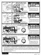
3-Pole, 20 Amp., heavy duty switch encased in waterproof receptacle. Two poles of switch control motor and third pole controls solenoid, isolat-
ing the two circuits to prevent solenoid kickback when switch is turned off. Refer to Figures 12 and 13 for recommended wiring installation.
SINGLE PHASE 1/2 HP
Factory Wired for 110-120-V A.C. unless otherwise specified. To connect for 220-240-V A.C. refer to information on inside face of
terminal box cover.
SINGLE PHASE
3
/
4
HP, 1HP, 1
1
/
4
HP, and 1
1
/
2
HP
Factory Wired for 220-240 volts. To reconnect for 110-120 volts refer to information on inside face of terminal box cover.
NOTE: After installation, be sure turntable rotates clockwise.
CAUTION
: When making field changes for voltage, be certain to change all other related electrical circuits such as solenoid valves, relays, etc.
ALL THREE PHASE MOTORS
3-Pole, 20 Amp., heavy duty switch encased in waterproof receptacle. Tap off any two leads for the solenoid valve. Refer to Fig. 14 and 15 for
typical wiring installation.
THREE PHASE
3
/
4
HP, 1HP, 1
1
/
4
HP, and 1
1
/
2
HP
All three phase motors are factory wired for 208-240-V A.C.
AFTER INSTALLATION BE SURE TURNTABLE ROTATES CLOCKWISE
. If not,
interchange any two of the three wires. To reconnect for 460 volts, refer to information shown on inside face of terminal box cover.
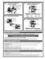
FIG. 8
OPTIONAL SUPPLEMENTARY
WATER CONNECTION
FIG. 10
INSTALLATION DIMENSIONS AND
DRAINLINE CONNECTIONS
FIG. 9
SWIRL SPRAY(S) ASSEMBLY
FIG. 11
SINK MOUNTED MODELS (SM)
500-1
= 18
7
/
16
1250-1
= 19
11
/
16
750-1
= 18
15
/
16
1250-3
= 18
15
/
16
750-3
= 18
7
/
16
1500-1
= 19
11
/
16
1000-1
= 18
15
/
16
1500-3
= 18
15
/
16
1000-3
= 18
7
/
16
FLOOR LINE
500-1SM = 17
11
/
16
750-1SM = 18
3
/
16
750-3SM = 17
11
/
16
FLOOR LINE
TOGGLE SWITCH
1/2” ELBOW
CLAMP
1” I.D.
FLEXIBLE
HOSE
1/2” GLOBE VALVE
SYPHON BREAKER MUST be
above Table Floor Level. Check
local code for confirmation.
1/2” SOLENOID VALVE
1/2” COLD WATER SUPPLY
JUNCTION BOX
AERATOR SPRAY
SPRAY GASKETS
STEEL WASHER
CONICAL –
BRASS WASHERS
NUT
LOCK
NUT
TUBING
LOCK
NUT
TUBING
NUT
STEEL WASHER
SPRAY HEAD
BRASS
WASHERS
SPRAY HEAD
GASKET
2
1
/
2
”
3
1
/
2
”
8
1
/
2
”
A
7
3
/
4
”
8
15
/
16
”
1
1
/
8
”
SLOPE =
1
/
4
” PER FOOT
3
9
/
16
”
3”
6”
8
1
/
2
”
A
7
3
/
4
”
8
15
/
16
”
2
5
/
32
”
SLOPE =
1
/
4
” PER FOOT
3
9
/
16
”
CONICAL
WASHER
{
{
A
A


