


Page 44 of 102
Page 45 of 102
Doc: DRX Installation
Version: 7.1 January 2021
Doc: DRX Installation
Version: 7.1 January 2021
DRX INSTALLATION MANUAL
DRX INSTALLATION MANUAL
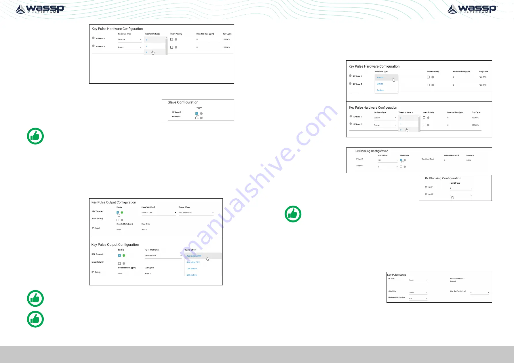
3.
If
HARDWARE
TYPE
selected is
Custom, set the
required trigger
threshold level.
THRESHOLD
VALUE
indicates a
sensitivity level to
the input signal.
4.
If the KP signal coming in is inverted select the
INVERT POLARITY
option.
5.
Under
SLAVE CONFIGURATION
select which key
pulse inputs DRX should transmit on. One, both or
neither key pulse input can be used.
NOTE: The input signal activity can be indicated using the DETECTED RATE
(ppm) and DUTY CYCLE monitors.
5.2.6.2. Configuring Key Pulse Master
In
MASTER
mode the DRX will transmit a key pulse signal based off the time of the DRX
transmit pulse. Equipment connected to DRX as slaves will transmit relative to this key
pulse.
To configure
MASTER
mode:
1.
Make sure that
KEY PULSE SETUP
mode is set to
MASTER
.
2.
Enable the Key
pulse transmit
under the
KEY
PULSE OUTPUT
CONFIGURATION
.
3.
Select time of
key pulse relative
to DRX transmit
time. The %
value indicates
the relative time
between DRX Txs.
NOTE: The output signal activity can be indicated using the DETECTED RATE
(ppm) and DUTY CYCLE monitors..
NOTE: Pulse Width is only used for Advanced Key Pulse Setting, described in
section
“5.2.6.4. Advanced Key Pulse” on page 45.
5.2.6.3. Configuring Key Pulse Blanking
Rx Blanking allows any data during the key pulse input period to be blanked out so
that potential interference is removed. This blanking will also remove potentially useful
acoustic return.
To configure Rx blanking:
1.
Under
KEY PULSE
HARDWARE
CONFIGURATION
select the
HARDWARE TYPE
.
2.
If
HARDWARE
TYPE
selected is
Custom set the
required trigger
threshold level.
3.
If the KP signal coming in is inverted select the
INVERT POLARITY
option.
4.
Enable the blanking
using the
BLANK
ENABLE
selections.
5.
The blanked region can be offset from the key
pulse input signal using the
HOLD OFF
selection.
NOTE: The input signal activity can be indicated using the signal rate and duty
cycle monitors.
5.2.6.4. Advanced Key Pulse
Advanced key pulse functionality can be enabled by applying the AKP license under
SYSTEM FEATURES
.
The advanced key pulse functionality includes:
»
KP TIMEOUT
; If no key pulse is identified over a given period DRX will revert to
standard operation.
»
JITTER
; Jitter can be configured in
order to decorrelate transmit while
maintaining synchronisation through
key pulse operation.
Jitter Slot width for key pulse output is controlled by the
PULSE WIDTH SETTING
under
KEY PULSE OUTPUT CONFIGURATION
.
JITTER SLOT PADDING
can be used to increase the width of Jitter Slots.


