background image

MANUAL OF USE AND MAINTENANCE

ORIGINAL INSTRUCTIONS

WASP 4070 HDP

Содержание 4070 HDP

Страница 1: ...MANUAL OF USE AND MAINTENANCE ORIGINAL INSTRUCTIONS WASP4070HDP ...

Страница 2: ...ieve the best results from WASP 4070 HDP No part of this publication may be reproduced stored in a filing system or transmitted to third parties in any form or by any means without the Manufacturer having issued a prior written authorization The Manufacturer reserves the right to make changes to its products at any time and without notice in order to constantly increase the quality therefore this ...

Страница 3: ...7 PRINTING board 40 5 2 8 TUNE menu 41 5 2 9 Digit window 42 5 3 First start 43 6 First use of the printer 44 6 1 General warnings 44 6 2 Preparing the 3D file 44 6 3 Slicing software 44 6 4 Autocalibration 45 6 5 Loading unloading of the material 45 6 6 Placing the printing plate on the vacuum bed 46 6 7 Selecting gcode 46 6 8 Function during the print 46 6 9 Removal of the printing plate 46 6 10...

Страница 4: ......

Страница 5: ...l must always be available for consultation in copy and by the recipient on the printer itself or in its immediate vicinity In the second case the location of the manula must me indicated on the printer clearly The Manual is susceptible to updates which appropriately classified will be transmitted to the user owner in order to update the consultation copy s The recipient must ensure that the perso...

Страница 6: ... is mandatory to keep this manual and all attached documents in an easily accessible place near the printer and known to all users operators and maintenance personnel Operators and maintenance technicians must be able to quickly find and consult the manual in any situation The manual is an integral part of the printer for security purposes Therefore It must be kept intact in all its parts It must ...

Страница 7: ...ifiedbymeansofanidentificationplateoftheManufacturerasrequiredbytheMachinery Directive In case of damage the Recipient must commission a copy Legend 1 Stampante 3D 3D printer 2 Modello Model 3 Rif TCT Reference 4 Input input power 5 Potenza Max Maximum power absorption 6 Corrente a pieno carico full load current 7 Anno di Produzione Year of production 8 Numero di serie Serial number 220v 240v Stam...

Страница 8: ...moval of defects under warranty are the responsibility of the Manufacturer except in cases where the nature of the defect is such that it can be easily removed on site by part of the Customer All consumables are excluded from the warranty The court of competent jurisdiction for any legal dispute is the Court of Ravenna Italy NOTE The guarantee lapses in the following cases Default or other contrac...

Страница 9: ...s on the printer can include Mechanical Electrical MECHANICAL NATURE INTERVENTIONS Any intervention of a mechanical nature must be carried out in strict compliance with the directives required by currentsafetyregulations Itisabsolutelyforbiddentoperformanytypeofmechanicalmaintenanceintervention on the printer during the operating cycle or in any case with parts of the printer moving Everymechanica...

Страница 10: ...ems are present as a standard in all machines and shall not for any reason be manipulated nor damaged Upon seeing abnormalities in the fuctions of these systems the user is responsible of reporting them to the Manifacturer who ll fix it Anytime the fuctions of these systems are compromised the machine must not be used for no reason as it may be dangerous for the user and may lead to major damages ...

Страница 11: ...er Maintanance Cleaning Maintenance cleaning operations must be carried out by trained and authorized personnel Operations must be performed in a safe stop condition disconnecting the printer from power sources Refer to chapter 7 Ordinary and Extraordinary Maintenance Legend Hot surfaces pay attention not to touch when heated ...

Страница 12: ...entrusted to him who has responsibility for the job Below is a description of the professional profiles for the operators involved in the printer User Qualified personnel able to perform simple tasks trained on using the printer He she supervises the proper functioning of the same and the eventual first intervention in case an alarm condition occurs Mechanical maintenance technician Qualified tech...

Страница 13: ...rations in which there is the possibility of causing damage to the environment NOTE Indicate the notes warnings suggestions and other points on which you want to draw the reader s attention or complete the explanation with further information Personal protective equipment PPE The graphic symbols used in this manual are indicated below to indicate the need to wear certain PPE PROTECTIVE GAUNTLETS I...

Страница 14: ...INTRODUCTION WASP S r l 1 14 1 ...

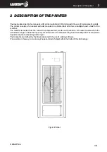
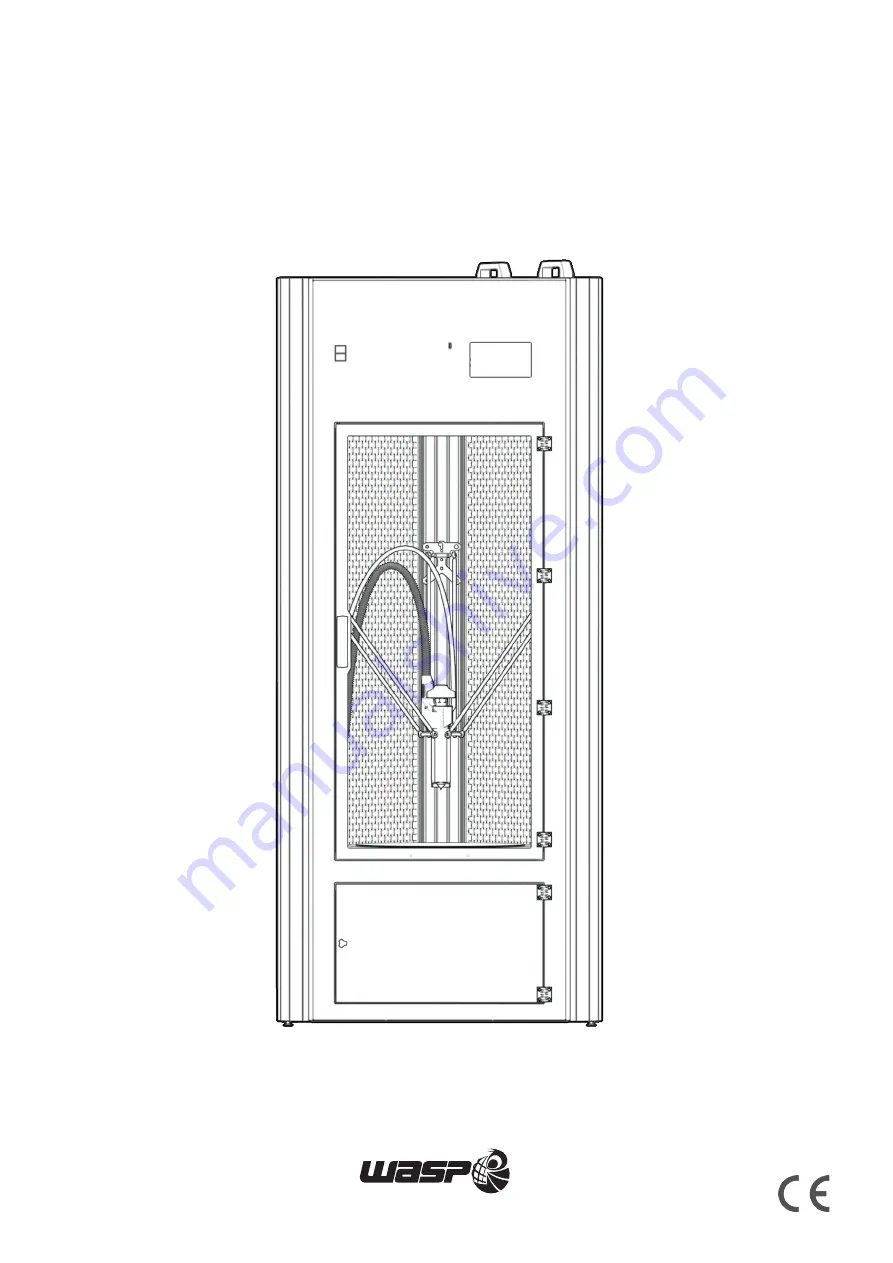
Страница 15: ... and a tank for the material The material is loaded from the tank with compressed air molten and pushed to the heated nozzle where it s extruded through a nozzle that lays very small amounts of material starting from the build plate The material is deposited by the toolhead layer after layer The toolpaths are defined by the file produced with the use of a slicing software It s possible in this way...

Страница 16: ... status of the printer allowing a quick visualization LED color State Situations Green Operational Machine turned on and ready to operate or print concluded White Printing Machine busy in a printing process Yellow Paused Machine paused or waiting for a material refill Red Cancelling error Machine cancelling an operation or sending an error message 4 TFT touch Operator display see paragraph 5 2 Use...

Страница 17: ...ion of the printer 2 Fig 2 2 Work area 2 2 Work area Legend 1 Cable carrier 2 Door handle 3 Carbon fiber rods 4 Material hose 5 HDP Extruder 6 HEPA filters 7 Chamber heaters 8 Sliders 9 VACS Vacuum Active Control System see paragraph 8 12 ...

Страница 18: ...scription of the printer 2 Fig 2 3 External area of the printer 2 3 External area of the printer Legend 1 Ethernet door for static IP cable connection 2 Material tank 3 Label 4 Power socket 5 TFT touch Operator display 6 Storage area ...

Страница 19: ... regulator knob 3 Loading material button 4 Material level bar 5 Discharge opening 6 Pressure gauge 7 Compressed air inlet connect with a flexible hose of 8 mm of external diameter from the compressor 8 Moisture filter 9 Material outlet connected with material hose in par 2 2 Work area Fig 2 4 Material storage area ...

Страница 20: ...ODUCTION WASP S r l 2 20 Description of the printer 2 Fig 2 5 VACS Vaacum active control system 2 5 VACS Vacuum Active Control System Legend 1 Aluminum vacuum bed 2 Silicon gasket 3 Removable printing plate ...

Страница 21: ...INTRODUCTION WASP S r l 3 21 Description of the printer 3 Fig 2 6 Extruder 2 6 Extruder Legend 1 Pellet hose 2 Extruder screw 3 Pellet hopper 4 Heatsink 5 Barrel 6 Cooling fan 7 Nozzle 1 3 5 7 4 2 6 ...

Страница 22: ...er max 120W Heated bed max 1300 W Heated chamber max 1500 W Compressed air requirements Input 5 bars Minimum volume 10 l recommended 50 l 8 mm inlet hose Use features Environment of use 20 30 C Warehouse 0 30 C Nozzle max 280 C Heated bed max 120 C Heated chamber max 50 C 3D printing informations Technology FFF Cilindric build area Ø 400 x 600 mm Nozzle diameter standard 1 mm Layer resolution 200 ...

Страница 23: ...seforwhichitwasdesignedandconstructeddescribed in paragraph 2 6 Failure to comply with safety regulations Operation of the printer with procedures other than those described in this manual Use components not provided for in the design phase Failure to comply with established maintenance schedules Perform work on the printer that involves the modification of components or parameters that affect the...

Страница 24: ...ns the operator must wear all the necessary Personal Protective Equipment PPE 3 1 1 Delivery of the printer Upon receipt make sure that The printer has not been damaged during transport Any packaging has not been tampered with consequent removal of parts from the inside The supply corresponds to the order specifications NOTE If the printer needs to be stored for a certain period of time before ins...

Страница 25: ...r ATTENTION Theweightoftheprinterisshowninparagraph2 4 Technicaldata Itisthereforenecessarytouse the lifting equipment whose expected flow is adequate for the weight to be lifted ATTENTION As long as the printer is not completely raised it is advisable to check the correct balance of the same During lifting all the area around the printer is considered dangerous ATTENTION All small equipment that ...

Страница 26: ...o damage them Remember that the original packaging of the machine is to be conserved for the entire life cycle of the product When this operation is completed the machine will be laying on the base pallet only fig 3 2a Beforehandlingthemachinemakesuretoremovethewoodenfixtureplacedclosetotheextremityofthemachine Don t throw this component away as it s part of the packaging and needs to be stored DO...

Страница 27: ... operators1 and 2 will push the machine from its top in horizontal direction until it overhangs about 30 cm from the pallet fig 3 2c Using the two handles positioned on the top of the machine the operators 1 and 2 will start lifting the machine The operator 3 will guide the machine on the other side preventing it from sliding fig 3 2 d ...

Страница 28: ...hine The operator 3 will guide the machine on the other side helping the edge to gently lay on the ground fig 3 2e Using the two handles positioned on the top of the machine the operators 1 and 2 will continue lifting the machine The operator 3 will guide the machine on the other side preventing the machine from falling freely In this phase is especially important to pay attention to the feet fig ...

Страница 29: ...3willhelpthemachinetogentlylayontheground In this phase is especially important paying attention to the feet fig 3 2g Now the machine is standing Move it on the floor by pushing in 2 people Ifthemachinemustbemovedinmorecomplexwayscarryouttheseoperationswithmaximumcareandattention Do not ever for any reason move the machine without the following recommendations fig 3 2h ...

Страница 30: ...ult on the machines Assemble the wheels on the bottom of the machine during the phase showed in fig 3 2b using the screws included Notice that one of the wheels is provided without brake this has to be placed on the top edge of the machine as its laying on the pallet as displayed in fig 3 2i ATTENTION If the optional wheels are assembled before any handling of the machine make sure to lock the bra...

Страница 31: ... necessary to prepare the necessary operating space by referring to the dimensions expressed in mm given in paragraph 2 4 Technical data The room must also be Equipped with the appropriate power supply line Installed in environments with brightness equivalent to that expected for industrial environments as indicated by the regulations in force in the country of destination with regard to safety in...

Страница 32: ...stics of the printer can be found in the manual see paragraph 2 4 Technical data Before connecting the printer s power cord to the electrical outlet check that the system s power consumption and voltages are suit 4 3 Pneumatical connection ATTENTION The operations related to these activities must be performed by authorized and professionally qualified personnel ATTENTION It is up to the user to pr...

Страница 33: ...tents of paragraph 1 6 General safety warnings Furthermore the specific requirements for safe interaction with the printer related to this chapter are detailed in the following paragraphs ATTENTION The operations related to these activities must be performed by authorized and professionally qualified personnel ATTENTION During operations the operator must wear all the necessary Personal Protective...

Страница 34: ...der temperature click to set new target temperature 2 Barrel temperature click to set new target temperature 3 Heated bed temperature click to set new target temperature 4 Wifi connection when connected shows network and IP for the machine When connected the WIFI icon is green when disconnected the icon is red 5 State of the machine v Autocalibration ENABLED DISABLED 6 Heated chamber click to set ...

Страница 35: ...purge of the extruder with a timer set at 20 minutes Stop it anytime with the button STOP The temperature is to be set before the Clean extruder command 3 Vacuum System Enables or disables VACS Vacuum Active Control System The switch shows current state ON or OFF Learn more in paragraph 8 12 VACS Vacuum Active Control System 4 Start print access to gcodes list to proceed with the printing see par ...

Страница 36: ...he PREPARE button in the toolbar Legend Free Zeta system enters in Free Zeta System Learn more in paragraph 8 6 Free Zeta System Disable motors disables all stepper motors on the machine Autocalibration Perform autocalibration procedure see par 8 2 Autocalibration Fig 5 2 3 Menu PREPARE BACKTOMAINBOARD ...

Страница 37: ...rdinarely with the instructions of the Manufacturer Legend SETTINGS Delta Settings Continuous print Extruder settings Motion settings Temperature settings Bed touch Filament sensor Out of Plate Blocking Access information WIFI settings MODE Send arbitrary commands Reload UI Test Mode Camera TOOLS Set Z Max Manual Control Manual Levelling Fig 5 2 4 Menu ADVANCED BACKTOMAINBOARD ...

Страница 38: ...earn more in paragraph 8 9 Network and printing server Legend 1 SSID to chose the desired network between all visible ones Static IP aption available with cable 2 PWD Allows to insert a password if present 3 AUTH makes you specify what kind of connection you re working with 4 USER Allows to insert use if present Clicking UPDATE the machine restarts with new settings Fig 5 2 5 WIFI settings BACKTOM...

Страница 39: ...ing GCODE you can launch gcodes and moving them from the USB to the printer The gcodes are loaded in the machine as explained in detail in paragraph 8 7 Loading gcode Legend 1 Chose to navigate USB Drive 2 Chose to navigate Printer Drive 3 GO launchs selected print Fig 5 2 6 GCODE BACKTOMAINBOARD ...

Страница 40: ...d print time left percentage of layers processed When the machine is connected the WIFI icon is green when disconnected the icon is red 5 State of the machine OPERATIONAL PRINTING PAUSE CANCELLING Autocalibration ENABLED DISABLED 6 Heated chamber click to set new target temperature Door OPEN CLOSED When VACS is active VACUUM icon is green when disabled the icon is white PAUSE Pause the print with ...

Страница 41: ...d in the machine until next reboot Legend 1 IP ADDRESS and network 2 Feedrate definesthespeedoftheprocess standardis100 totuneituse and buttonandwait3seconds 3 Flow defines the amount of the flow standard is 100 to tune use and button and wait 3 seconds 4 Fan allows to set an user defined value for the fan standard is 0 and max is 255 to tune use and button and wait 3 seconds NOTE this value doesn...

Страница 42: ...Preparing to use the printer 4 5 2 9 Digit window The digit window is used when is necessary to define a numeric value Use the button to digit the desired value and confirm with the green button SET Use the CANC button to erase a digit Use BACK to exit the digit window ...

Страница 43: ...socket it is necessary to perform some operations in order to allow the printer to work Belt stop clamps Inside the printer there are three belts necessary for moving the extruder during printing To avoid movements of the extruder during transport clamps are applied on the straps this have to be removed before starting the print ...

Страница 44: ...e Equipment PPE NOTE Visit the website www 3dwasp com en download for the updated printing profiles user manuals and useful resources for the use of the machine 6 2 Preparing the 3D file Make sure that the 3D model follows these guidelines Watertight manifold geometry and absence of defects Correctly scaled Exported in stl format binary is generally to prefer 6 3 Slicing software The slicing softw...

Страница 45: ...suretocleanthebedandtheextruder itwillstarttheprocedure that will last a few minutes Learn more on the Autocalibration procedure on paragraph 8 2 Autocalibration 6 5 Loading unloading of the material For better understanding of the components mentioned in the procedure below read carfully the paragraph 2 4 Tank material storage To load the material proceed as follows 1 Verify the discharge opening...

Страница 46: ...Selecting gcode Select the printing file from PRINT GCODE Choose USB DRIVE to navigate the file in the external drive or PRINTER DRIVE to navigate the files saved in the internal storage of the printer Printing will start as soon as the printing bed and the extruder reach the pre set temperatures After launching the print the USB drive can be removed as the gcode is copied in the internal drive 6 ...

Страница 47: ...fic requirements for safe interaction with the printer related to this chapter are detailed in the following paragraphs ATTENTION The operations related to these activities must be performed by authorized and professionally qualified personnel ATTENTION Payparticularattentionduringthevariousstagesoftheprocedures itisessentialtoweargauntlets because there is a risk of burns ATTENTION During operati...

Страница 48: ...connecting the printer from the power source by unplugging the power plug NOTE In case of replacement of components during maintenance they must be replaced with identical and original components ATTENTION During operations the operator must wear all the necessary Personal Protective Equipment PPE Part Kind of intervention Period Procedure Belts Tension control 160 h Par 7 2 1 Arms ball joint Lubr...

Страница 49: ...o perceive an important difference in tension on one of the belts contact the Manufacturer addressing support 3dwasp com Fig 7 3 1 Ball joints lubrication Fig 7 2 1 Monitoring the tension of the belts 7 2 2 Ball joints Lubrication Turn off the machine and open the door Check the mobility stiffness of the arm joints Apply machine tool lubricant and gently move them manually Wipe off excess oil This...

Страница 50: ... top of the machine on the heaters All the fans should work at minimum speed when the machine is turned on If one or more of the fans are not working contact the Manufactureraddressing support 3dwasp com 7 2 4 Sliders Check plays Check that the arm sliders do not have any play between them and the sliding aisle if it is present contact the Manufacturer Fig 7 2 4 Check plays on the sliders ...

Страница 51: ...INTRODUCTION WASP S r l 51 Ordinary and extraordinary maintanance ...

Страница 52: ...52 Ordinary and extraordinary maintanance 7 2 5 Nozzle Changing the nozzle Changing nozzle is only recommended when The print looks inconsistent due to a clogging The nozzle is damaged or consumed Fig 7 2 6 Cleaning the nozzle ...

Страница 53: ...ibed in par 7 2 8 Ooze shield protection 4 Unscrew and remove the nozzle using the provided tool pay attention to the hot surfaces 5 Tighten back the new nozzle fixing it in its position 6 Fix the Silicone Ooze shield protection as described in par 7 2 8 Ooze shield protection 7 Use the PRINT CLEAN EXTRUDER command After a nozzle replacement is recommended to perform the Autocalibration procedure ...

Страница 54: ... country and region The replacement of the HEPA filter is carried out with the machine turned off 1 Open the printer door 2 Unscrew the knob securing the protective plate of the first HEPA filter 3 Remove the HEPA filter protection plate by gently pulling towards the door 4 Use the retaining clip to remove the HEPA filter 5 Insert in the new HEPA filter 6 Reassemble everything in reverse order 7 R...

Страница 55: ...fig 7 2 8 c fig 7 2 8 d fig 7 2 8 e fig 7 2 8 f INTRODUCTION WASP S r l 55 Ordinary and extraordinary maintanance Fig 7 2 9 Replacement of HEPA filters ...

Страница 56: ... the filter fig 7 2 7 7 2 8 Ooze shield protection The Oooze shield protection serves to cover the hot part of the extruder from the cooling flow and to prevent the rise of plastic material during the print If the protection gets damaged it may need to be replaced The replacement procedure involves these steps 1 Unhook the protection from the left side fig 7 2 8 a 2 Unhook the protection from the ...

Страница 57: ...INTRODUCTION WASP S r l 57 Ordinary and extraordinary maintanance fig 7 2 8 a fig 7 2 8 b fig 7 2 8 c fig 7 2 8 d Fig 7 2 8 Ooze shiled protection ...

Страница 58: ...arranty null and void Extraordinary maintenance interventions are those that are carried out On the occasion of exceptional events such as revisions Stopping due to breakage of mechanical or fluid parts For additional information support and FAQs on our website www 3dwasp com support ATTENTION During operations the operator must wear all the necessary Personal Protective Equipment PPE ATTENTION Pa...

Страница 59: ...INTRODUCTION WASP S r l 59 Ordinary and extraordinary maintanance ...

Страница 60: ...ign matter in the pellet loaded inside the extruder material not compatible with the extruder for example with aggregates that prevent extrusion incorrect process settings and temperatures extruder failure To carry out the procedure carefully follow the instructions below 1 Turn off the machine 2 Unscrew the three screws on the pellet hopper fig 7 3 1 a b with a 2 5 mm Allen key 3 Remove the pelle...

Страница 61: ...INTRODUCTION WASP S r l 61 Ordinary and extraordinary maintanance fig 7 3 1 c fig 7 3 1 d fig 7 3 1 e fig 7 3 1 f Fig 7 3 1 Cleaning the screw ...

Страница 62: ...crew assembly fig 7 3 1 i This operation is not possible without heating the extruder Pay attention to the hot and liquid material on the screw during extraction Also make sure that the bearing on the screw is removed together with the assembly fig 7 3 1 l m 10 With the help of pliers remove the material from the screw before it returns to solidify completely 11 Once cleaned put the screw back in ...

Страница 63: ...INTRODUCTION WASP S r l 63 Ordinary and extraordinary maintanance fig 7 3 1 i fig 7 3 1 l fig 7 3 1 m fig 7 3 1 n Fig 7 3 1 Cleaning the screw ...

Страница 64: ...rts To carry out the procedure carefully follow the instructions below 1 Turn off the machine 2 Remove the hose from the material outlet on the tank fig 7 3 2 a 3 Slide the hose from inside the machine until it is completely inside fig 7 3 2 b 4 Remove the hook and loop fasteners on the cable guide one by one fig 7 3 2 c 5 Remove the cable guide from the extruder fig 7 3 2 d 6 Carefully remove the...

Страница 65: ...fig 7 3 2 c fig 7 3 2 d fig 7 3 2 e fig 7 3 2 f INTRODUCTION WASP S r l 65 Ordinary and extraordinary maintanance Fig 7 3 2 Replacing the Extruder ...

Страница 66: ...ntanance 7 Unscrew the six screws securing the arms 8 Remove the arms from the extruder one by one 9 Remove from the machine the whole extruder in its entirety with the assembled hose To assemble a new extruder repeat the above steps in reverse order Fig 7 3 2 Replacing the Extruder ...

Страница 67: ...INTRODUCTION WASP S r l 67 Ordinary and extraordinary maintanance ...

Страница 68: ...nd in ADVANCED TOOLS MANUAL LEVELING Based on the three point principle the machine moves the tool to the vertices of an equilateral triangle proportional to the aluminum bed fig 7 3 2 a At each point by rotating a screw the distance between the tool and the bed is adjusted fig 7 3 2 b c d e Use a piece of paper 80 90 gr as thickness between the bed and the nozzle Once completed verify that the he...

Страница 69: ... WASP S r l 69 Ordinary and extraordinary maintanance fig 7 3 2 c fig 7 3 2 d fig 7 3 2 e fig 7 3 2 f Fig 7 3 2 Manual Leveling The figures represent the exact same manual leveling procedure on a different machine ...

Страница 70: ...INTRODUCTION WASP S r l 70 Ordinary and extraordinary maintanance ...

Страница 71: ...g bed Right printing plate or glue based on the material to be printed Adequate speed flow and nozzle temperature in the first layer Adequate printing floor temperature basing on the material to be printed It is recommended to monitor the adhesion between first layer and bed during the first minutes of each print In order to control the sticking on the first layer some print settings can also be u...

Страница 72: ... nozzle on the bed so that they touch 5 Use the command PREPARE AUTOCALIBRATION 6 Notice AUTOCALIBRATION ENABLED message on the main window 8 2 2 Launch Autocalibration After the procedure to enable the Autocalibration paragraph 8 2 1 the actual Autocalibration command can be started using the command PREPARE AUTOCALIBRATION The printer will start to heat up nozzles and bed The autocalibration wil...

Страница 73: ... timer that can be viewed on the display the extruder will stop turning automatically after a certain time It is possible to stop the operation prematurely with the STOP button on the display Thorough cleaning To clean the screw of any debris or remnants of previous material it is also possible to remove the nozzle as indicated in par 7 2 5 Nozzle and then launch the command without an extruder Re...

Страница 74: ...rint The nozzle stopped during printing but the machine has continued to print The cases in which it is not possible to recover the print are when The printed part detached the printing floor The printed part broke during the press The deformation of the piece is such that it is not possible to recover the print To run the Free Zeta system correctly 1 Activate the VACS paying attention not to move...

Страница 75: ...INTRODUCTION WASP S r l 75 Use of the printer Fig 8 4 Free Zeta System ...

Страница 76: ...ch for your file s name and select it for printing 11 Once the printing has started the file is saved inside the machine s memory and the USB pendrive can be removed 8 6 2 Loading with Wi fi Access the printer server from your browser Enter the Control page and click on Upload gcode Choose the gcode in your device Wait for the gcode to load After being loaded the file is selectable for printing If...

Страница 77: ...INTRODUCTION WASP S r l 77 Use of the printer Fig 8 7b Loading the gcode on printer server Fig 8 7a Loading gcode from USB pendrive ...

Страница 78: ...opening is closed and the tank is empty 2 Open the tank s lid by using the opening handle fig 8 6 a 3 Load with the pellets up to 5 cm from the tank s lid fig 8 6 b 4 Use the pressure gauge to increase the pressure to 5 BARs 5 Force the loading of the pellets by clicking the loading material button on the tank until the extruder is filled 6 Set the temperatures for nozzle and barrel compatibly wit...

Страница 79: ...INTRODUCTION WASP S r l 79 Use of the printer fig 8 6 c fig 8 6 d fig 8 6 c fig 8 6 d Fig 8 6 Loading the material ...

Страница 80: ...e the movement in the specified direction Remember that whenever the machine touches an endstop the operation will be aborted EXTRUDING or RETRACTING E axis The procedure for moving X Y or Z axis is 1 Assign the extruder to move a target temperature depending on the material loaded 2 Use the command PRINT AUTOHOME 3 Access ADVANCED TOOL MANUAL CONTROL 4 Select from the bar on the top the desired s...

Страница 81: ...INTRODUCTION WASP S r l 81 Use of the printer fig 8 6 Manual control command inside Prepare menu fig 8 6 Manual extrusion of the filament ...

Страница 82: ...ly configure the printer In case a manual configuration is required FIXED IP it will be possible to do it through the WIFI configuration by selecting NOWIFI STATIC IP When the wifi settings are set the machine will try to automatically reconnect to the saved wifi network as it is turned on 8 9 3 Printer server Once the machines is connected to the network can be controlled through a computer s bro...

Страница 83: ... Camera for remote monitoring of the print on the first layers Monitoring of the printer in Operational state Monitoring of the printing process in Printing state Gcode viewer with real time advancement Terminal for monitoring and arbitrary commands Control of the temperatures Nozzles Heated bed heated chamber Even if the print server architecture contains functions other than those mentioned abov...

Страница 84: ...e is essential for good operation This value is automatically saved by the machine during autocalibration After the AUTOHOME command it is possible in the main board to see among the values shown the Z max saved in the machine indicated as Z The command for manually setting a Z Max value can be found inside ADVANCED TOOLS Set Z max fig 8 10 a With a scale value of 100 click on the Z arrow making t...

Страница 85: ...INTRODUCTION WASP S r l 85 Use of the printer Fig 8 10a SET Z MAX window Fig 8 9 Resurrection system banner Fig 8 10b SET Z MAX procedure ...

Страница 86: ...bility to reach the vacuum 2 Place the silicone gasket in its slot fig 8 12b 3 With the door closed activate the vacuum with the PRINT VACUUM command The switch should change from OFF to ON 4 Once clicked the command will show the switch to ON and the pump will start working 5 Open the door and place the removable printing plate on the gasket centered 6 Help the positioning by applying light even ...

Страница 87: ...INTRODUCTION WASP S r l 87 Use of the printer Fig 8 12 a Clean the aluminum vacuum bed Fig 8 12 b Placing the silicone gasket Fig 8 12 c Position the removable printing plate ...

Страница 88: ...ATTENTION During operations the operator must wear all the necessary Personal Protective Equipment PPE 9 2 Disposal and dismantling Intheeventthattheprintershouldbetakenoutofserviceforaprolongedperiodwhilewaitingforthedismantling it is advisable to indicate its presence preventing unauthorized access to the printer Before starting the dismantling operations it is necessary to create around the pri...

Страница 89: ... destination concerning the disposal of waste so it is forbidden to disperse in the environment any type of processing residue oils etc subdividing the dismantled parts by type for a correct separate collection of materials NOTE Within the European Community electrical equipment must be disposed of as prescribed by the European Community Directive 2012 19 EU on waste electrical and electronic equi...

Страница 90: ...____ __________________________________________________________________________________ __________________________________________________________________________________ __________________________________________________________________________________ __________________________________________________________________________________ _______________________________________________________________...

Страница 91: ..._ __________________________________________________________________________________ __________________________________________________________________________________ __________________________________________________________________________________ __________________________________________________________________________________ __________________________________________________________________...

Страница 92: ...WASP S R L Via Castelletto 104 48024 Massa Lombarda RA Italia www 3dwasp com info 3dwasp com ...

Отзывы: