background image


Wash Thermostat 


Part Number 

30201 

Function 

Controls the wash element  

Description 

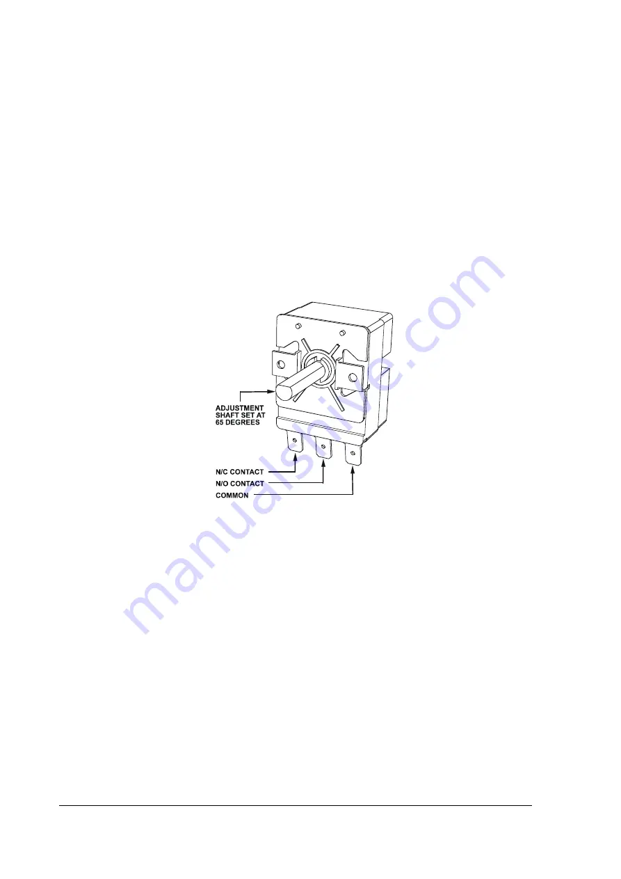
The wash thermostat is a single pole capillary type device. It has a single changeover contact 
and a rotating shaft for a manual temperature adjustment.  
 
Factory default setting is 65°C. 
Contact switching capacity: 16(4) A 380 V.  


Diagram


Replacement 

Drain the wash tank. Take note of the connections to the wiring loom before 
disconnecting. Release thermostat’s gland nut, move the capillary bulb out of the mounting 
bracket inside the tank and remove the bulb from the wash tank (remove the probe from 
the pocket in the wash tank on the models supplied with a pocket for the thermostat 
probe). Replace in reverse order.  
 

Adjustment 

Insert the probe of a digital thermometer into the wash tank. Check the thermostat settings 
on a temperature rise. Adjustment is performed by rotating the adjustment shaft of the 
thermostat. Clockwise rotation of the shaft increases the setting, anticlockwise– decreases it.  
 

NOTE

: the adjustment shaft in a flat horizontal position is a factory default setting 

corresponding to 65°C (see the diagram).  


Service Manual XP3

15

Revision 1F

Содержание XP Series

Страница 1: ...XP PASSTHROUGH DISHWASHER SERVICE MANUAL...

Страница 2: ...Service Manual XP3 2 Revision 1F...

Страница 3: ...noid Valve 16 Pressure Switch 17 Wash Pump 18 Detergent Pump 19 Rinse Aid Injector 20 Electronic Timer 21 Assembly Electrical Diagrams 26 Wiring Tray Assembly 26 Control Panel Assembly 27 Wash System...

Страница 4: ...Service Manual XP3 4 Revision 1F...

Страница 5: ...before connection Poor quality supply or excessive water hardness may affect performance or damage machine filtration and or softening is recommended Flow rate minimum 20 litres per minute Pressure b...

Страница 6: ...NOTE If uncertain please consult a chemical specialist for assistance in selecting the right chemicals and calibrating machine settings to suit this along with your unique site conditions and require...

Страница 7: ...Installation Diagram XPD Installation Diagram Part WXP0031 Date 16 07 19 Version 1 A Service Manual XP3 7 Revision 1F...

Страница 8: ...WASTE CHEMICALS CHEMICAL NAME CONTAINER NO LEAKS PRIMED CALIBRATED DETERGENT RINSE FLUID MACHINE OPERATION MACHINE RUNNING CORRECTLY MULTIPLE CYCLES RUN NO ISSUES CHEMICAL DOSAGE CORRECT CORRECTLY FLO...

Страница 9: ...Service Manual XP3 9 Revision 1F...

Страница 10: ...Service Manual XP3 10 Revision 1F...

Страница 11: ...k the rinse fluid dosage is not too high If uncertain please consult a chemical specialist Check detergent dosage is within the requirements Dishwasher is foaming Ensure there is no other soap being t...

Страница 12: ...n foaming commercial detergent and drying agent do not use domestic detergents which will cause the wash tank to foam 7 Operator Use Guide START Turn on at wall Ensure the Upstand 3 and Wash Pump Filt...

Страница 13: ...nse Tank Assembly 6 Wash Pump 7 Solenoid Valve 8 Wash Element 9 Wiring Tray Assembly 10 Electronic Timer 11 Contactor 12 Door Relay 13 Wash Thermostat 14 Rinse Thermostat 15 Detergent Pump 16 Rinse Ai...

Страница 14: ...disconnecting Move the capillary bulb out of the thermostat pocket inside the rinse tank Replace in reverse order Adjustment Remove the capillary bulb of the temperature gauge out of the rinse tank po...

Страница 15: ...bulb out of the mounting bracket inside the tank and remove the bulb from the wash tank remove the probe from the pocket in the wash tank on the models supplied with a pocket for the thermostat probe...

Страница 16: ...ater Diagram Replacement Disconnect the wires from the solenoid connectors Remove hot water supply hose Release a hose clamp on the outlet solenoid hose and remove the hose Slide the solenoid valve up...

Страница 17: ...ould cease filling when the water attains a level about 10mm below an overflow level of the upstand Adjust fill level if necessary by Level adjusting screw on the pressure switch Select drain cycle re...

Страница 18: ...PTION PART ITEM DESCRIPTION PART 1 Volute 600 41116 7 O ring 600 41113 2 Pump flange 600 41117 8 Screw 3 Fixed seal 600 41110 9 Plug screw 4 Rotating seal 600 41111 10 O ring plug 5 Impeller 600 41115...

Страница 19: ...tergents are hazardous To replace complete pump disassemble the pump after unscrewing two screws from the support bracket assemble the new pump in reverse order To prime pump drain and refill the mach...

Страница 20: ...glasswasher using 2 6 litres per cycle The volume of rinse fluid required will depend on factors such as product type water hardness and whether glasses or dishes are being washed but about 0 5 ml per...

Страница 21: ...Service Manual XP3 21 Revision 1F...

Страница 22: ...Service Manual XP3 22 Revision 1F...

Страница 23: ...9 RELAY 2 OFF 60 40 120 RELAY 3 ON Cold Rinse 60 40 120 RELAY 3 OFF 60 40 120 RELAY 4 ON Cycle Light Drain Pump 0 0 0 RELAY 4 OFF 60 40 120 RELAY 5 ON Detergent Pump 0 0 0 RELAY 5 OFF 30 30 30 RELAY 6...

Страница 24: ...70 RELAY 3 OFF 60 60 60 60 60 40 180 RELAY 4 ON 0 0 0 0 0 0 0 RELAY 4 OFF 60 60 60 60 60 40 180 RELAY 5 ON 0 0 0 0 0 0 0 RELAY 5 OFF 30 15 30 30 30 30 30 RELAY 6 ON 0 0 0 0 0 0 0 RELAY 6 OFF 30 30 30...

Страница 25: ...e cycle selected with MEDIUM time added to RELAY 1 OFF START 1 START 2 both off Heavy Cycle cycle selected with LONG time added to RELAY 1 OFF START 3 Pressure Switch Same as above THERMO Thermostop S...

Страница 26: ...ZP M4x6 8800 7 4 PCB SUPPORT END DOME HEAD 600 30527 8 1 CONTACTOR 20A 3NO NC 230 240V 600 30337 9 1 POWER SUPPLY TERMINAL LABEL LABEL 10 1 PERISTALTIC RINSE AID PUMP ADJUSTABLE 600 30480 11 1 PERIST...

Страница 27: ...Light Green 22mm 220VAC LED Stainless Steel 600 30528 6 2 TEMPERATURE GAUGE AG 903 600 30515 7 1 Switch Drain 22mm Maintained 2 Poles 220V Blue 600 30517 8 1 M4 X 10 S S WELD STUD 600 80088 9 DETAIL A...

Страница 28: ...SESPINDLE 2 18 1896 GASKETFOR40mmDRAINWASTE 1 Parts List ITEM PARTNUMBER DESCRIPTION QTY 19 6037 BACKNUT126x40mm 1 20 40010144 UPSTAND K 1 21 ARP205 O RING11IDx18OD 1 22 60080009 M10SSHXNUT 1 23 ARP32...

Страница 29: ...EM 10 HOSE CLAMP ASS05 8 1 SOLENOID VALVE 1 WAY 90 DEG 3342 9 1 VACUUM BREAKER 1 2 ASSY 600 60053 10 1 RINSE TANK SUPPORT BRKT 400 21088 11 2 WASH RINSE SPINDLE 400 30223 12 1 NON RETURN VALVE 600 304...

Страница 30: ...List QTY DESCRIPTION PART NUMBER ITEM 1 THUMB SCREW RETAINING PLATE 600 41191 1 5 JET GM5 RINSE 600 40049 2 1 JET GM5 BLIND RINSE 600 40050 3 8 PLASTIC WASH JET EP EU 600 40015 4 2 WASH RINSE ARM BUS...

Страница 31: ...MM 303 10017 1 2 TSTAT TY60 R 110C WITH E BKT 600 30088 2 1 STANDOFF M3 x 12 600 80064 3 1 ELEMENT RINSE 6kW 600 30496 4 3 WASHER FL SS 304 M8x16x1 2mm 600 80022 5 3 NUT NYLOC SS M8 600 80063 6 303 10...

Страница 32: ...328 10012 3 1 PASSTHROUGH DOOR STAY MOUNT 400 30225 4 1 M8x12 HEX HD SET SCREW T304 600 80029 5 1 PASSTHROUGH DOOR STAY ASSY 400 10206 6 1 8mm TYPE A SEALING WASHER 600 80158 7 1 M8x20 HEX HD SET SCR...

Страница 33: ...600 80030 1 2 NUT NYLOC SS M8 600 80063 2 1 RACK GUIDE ROD ASSEMBLY 328 10008 3 1 M2 RACKSLIDE SUB ASSEMBLY 328 10024 4 2 M5 x 12 SS HEX HEAD BOLT 600 80135 5 2 WASHER SPRING SS 304 M5 8567 6 328 1002...

Страница 34: ...Schematic Diagram XP 3 Schematic Diagram Part 090137 Date 25 05 2019 Version 1 D Service Manual XP3 34 Revision 1F...

Страница 35: ...XP3 W WIRING DIAGRAM IMPORTANT Service Manual XP3 35 Revision 1F...

Страница 36: ...4 Position 600 30269 Temperature Gauge 600 30546 Terminal Strip 5 Way 3229 Power Relay 600 30223 Timer Electronic 600 30513 Heating Components Over Temperature Thermostat 600 30088 Rinse Element 6 kW...

Страница 37: ...enoid Valve 3342 Wash Pump 600 30299 Rinse Pump 600 30400 Drain Pump 600 60102 Wash Tank Components Drain Upstand 400 10144 Rack Slide Assembly 328 10026 Wash Rinse Arm Assembly 600 41148 Scrap Tray 3...

Страница 38: ...Accessories XP3 Accessories Part XP3 ACW Date 04 12 2018 Version 1 B Service Manual XP3 38 Revision 1F...

Страница 39: ...RINSE PUMP KIT0440021 Service Manual XP3 39 Revision 1F...

Страница 40: ...ecure pump to base using M6 bolt 12 and spring washer 11 3 Assemble union 7 with gasket 6 onto machine waste connection Join to inlet hose and fit hoseclip Inside wash tank place filter 5 over waste c...

Страница 41: ...Revisions Manual Revisions REVISION REVISION FROM CHANGE STATUS DATE SERIAL NO DESCRIPTION Service Manual XP3 41 Revision 1F...

Страница 42: ...NOTES Service Manual XP3 42 Revision 1F...

Страница 43: ...NOTES Service Manual XP3 43 Revision 1F...

Страница 44: ...vice 1300 264 217 Parts 1300 263 107 Tel 03 9518 3888 Fax 03 9518 3818 E mail sales moffat com au web www moffat com au ISO9001 All Washtech products are designed and manufactured by Washtech using th...

Отзывы: