background image

INSTALLATION & USER MANUAL

5


Installation and User Manual 

5

Revision 8.12.2015

INSTALLATION of the SOLAR PANEL and RAIN SENSOR  

The  solar  panel  must  be  mounted  with  airspace 
underneath for cooling and performance efficiency; as 
well as maintain the product life span.  

1. Lay the solar panel face down on a flat surface. 

Take care not to scratch the solar panel. 

2. Insert two stainless steel nuts into the channel of 

the  perimeter  frame;  one  each  on  the  two  short 
sides. 

3. Use  two  stainless  steel  bolts  to  attach  the  two 

bracket  tabs  to  the  frame  with  the  two  nuts 
inserted into the channel. Do not fully tighten at 
this time. 

4. Use the remaining stainless steel bolts and nuts to 

attach the mounting bracket to the solar panel. 

5. Install  the  solar  panel  and  bracket  on  to  the 

exterior  of  the  building  near  the  operator 
installation location. 

6. Tilt  and  rotate  the  solar  panel  to  maximize  the 

solar  panels  exposure  to  the  Sun.  Alignment 
towards  the  southern  sky  is  recommended  for 
most  locations  in  North  America  for  best 
exposure to mid-day sun. 

7. Tighten all the fasteners to secure the solar panel 

orientation. 

8. Route  and  waterproof  the  pigtail  wiring  to  the 

interior of the building where the operator is to be 
installed. 

9. Install the rain sensor and bracket on the exterior 

as level as possible near the operator. 

10. Route  and  waterproof  the  wiring  to  the  interior 

where the operator will be installed. 

It  is  highly  recommended  to  only  use  the  wiring 
provided for the solar panel and rain sensor. 

1.  Review  the  separate  instructions  for  motor 

operation  and  open  the  skylight  fully  with  the 
remote control.

2.  Connect the solar panel to the wire on the exterior 

of the skylight at the low side. The connector can 
only  go  together  one  way  and  will  ‘click’  when 
locked together.

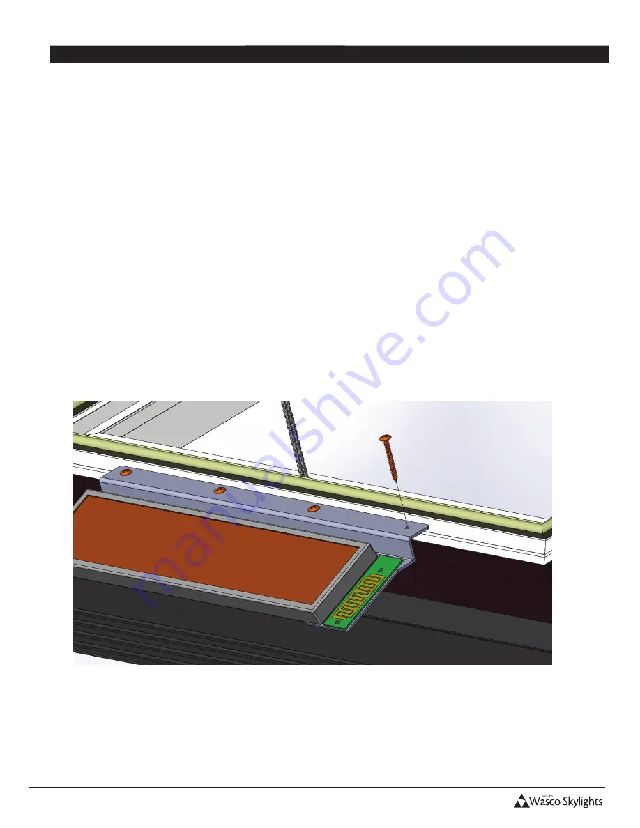
3.  Locate  the  solar  panel  on  the  skylight  frame  as 

shown below, centered side to side. Install the 
panel with the screws supplied.

4.  Close the skylight to complete the installation.

NOTE: The skylight needs to be installed on the roof before attaching the solar panel.

Содержание Solar Smart EVMS

Страница 1: ...MANUAL 800 388 0293 Fax 207 216 4562 csm wascoproducts com www wascoskylights com Eastern Facility 85 Spencer Drive Unit A Wells ME 04090 Western Facility 6645 Echo Avenue Reno NV 89506 with Rain Sensor MODELS EVMS GSVMS ...

Страница 2: ...chment link on chain is fastened to the sash by a release pin 7 AC trickle charger included 8 Adaptable to awning and hopper windows and skylights Remote Highlights 1 Large and readable display with bi directional feedback from the operator a Open Close status percentage displayed b Operator and remote battery level percentage displayed c Solar charge rate displayed in mA d Temperature display 2 9...

Страница 3: ...nd bracket g bracket ket tabs UIRED ing the operator ing the chain clip ing the solar panel and bracket DO NOT INSTALL THE BATTERIES UNTIL DIRECTED TO DO SO Chain Clip Battery Cover Operator Battery AC Trickle Charger Connector Lifting Chain Mounting Bracket SOLAR SMART OPERATOR SOLAR SMART REMOTE ...

Страница 4: ...e up the remote if the LCD display has powered off 2 Press ZONE to choose a single zone 1 thru 9 of operators or ALL to operate all operators in all zones 3 Press OPEN or CLOSE to open or close the window skylight 4 Press OPEN or CLOSE during operation to STOP the operator at any time Enable Disable Automatic Functions 1 Press and hold AUTO to show or remove AUTO from the display thus enabling or ...

Страница 5: ...r Manual sion 8 12 2015 ON of the SOLAR PANEL and RAIN SENSOR panel must be mounted with airspace for cooling and performance efficiency as intain the product life span e solar panel face down on a flat surface are not to scratch the solar panel two stainless steel nuts into the channel of rimeter frame one each on the two short wo stainless steel bolts to attach the two t tabs to the frame with t...

Страница 6: ...tion 7 ZONE ALL and the temperature should now be displayed Installation and User Manual 7 Revision 8 12 2015 INITIAL REMOTE SETUP and CONFIGURATION The following are applicable for configuring the main remote only To configure additional remotes refer to Multiple Remotes for more information Pressing MODE does not work when zone in remote display is set to ALL Press ZONE to exit zone ALL All step...

Страница 7: ...r The remote will need to be paired within 2 minutes or the operator will default back to the previous settings 1 Remove the battery cover from the operator If connected disconnect the battery connector from the operator circuit board for at least 30 seconds NOTE The Solar Panel must also be disconnected at this time 2 Connect the battery connector to the operator circuit board pressing firmly unt...

Страница 8: ...o operator zones ID numbers and or adding additional operators can only be performed using the main remote The changed settings would then need to be re sent from the main to the secondary remote s Ensure that a main remote has been configured as outlined in Remote Setup and Configuration and that it has been paired to the operator s as described in Paring Remote to Operator Secondary Remote Confi...

Страница 9: ...n from the main remote It will wait for 30 seconds 2 MAIN REMOTE STEPS a Press and hold MODE release when PAIR SET is displayed b Press MODE twice to move past RE ZONE to display M in the upper right corner as flashing c Press ENTER to begin transmitting the settings to the secondary remote d SUCC will be displayed on a successful transfer of settings i If a FAIL message is displayed instead be su...

Страница 10: ...y ON or OFF for one second then SUCC for 2 seconds indicating success Press MODE a few times to return to the home screen a If setting not successful LCD displays FAIL for 1 second then returns to the same step 8 to retry setting RAIN SENSOR OPERATION When a drop of water is on the sensor the operator may not react immediately The control system actually takes multiple reading in an effort to avoi...

Страница 11: ...function off 9 Press ENTER 10 ST is now displayed and flashing Press MODE to return to the home screen OR press to scroll and set other features 11 The Time To Close selection will be retained in memory until changed by the user However you must activate the AUTO feature for either the Time To Close or the Temperature Control TC function for it to operate NOTE The Time To Close and Temperature Con...

Страница 12: ...he operator s is open The factory setting MAX OPEN limit is set to open up to 80 of full open position 1 Press any key to wake up the remote if the LCD display has powered off 2 Press MODE 3 Press ZONE as necessary to choose the appropriate zone 1 thru 9 4 Press ENTER to save your selection 5 MAX OPEN will be displayed and flashing 6 Press ENTER 7 Press to set the percentage in increments of 10 8 ...

Страница 13: ... Press ENTER 8 Press to set the desired temperature or NULL to turn function off for this zone 9 Press ENTER to save your selection The temperature in which the operator will run has now been set Next a MAX OPEN limit is set specifically for when the TC function opens the operator This MAX OPEN cannot exceed the limit set for basic operation 10 Press to set the percentage in increments of 10 of th...

Страница 14: ...ular moment in time This measurement is highly variable and depends directly upon the level of sunlight on the solar panel Be aware of external influences which affect the light level these are direction and angle of exposure of the solar panel to the light source sky conditions clouds man made structures or trees which cause shadows on all or part of the solar panel and maintenance of the solar p...

Страница 15: ...when PAIR SET is displayed 3 Press MODE again to display RE ZONE 4 Press ZONE as necessary to choose the appropriate zone 1 thru 9 of the operator to be moved to another zone 5 Press ENTER to save your selection 6 Press to choose the ID number 1 thru 9 within the zone in which the operator is assigned to 7 Press ENTER to save your selection 8 SUCC will be displayed The operator will now be unassig...

Страница 16: ...ise set MAX OPEN 4 Temperature change must be maintained for 10 minutes before the temperature control TC function will operate For more Trouble Shooting Tips please visit www SolarSmartOpener com ADVANCED SERVICE OPERATIONS RESET OF REMOTE TO FACTORY SETTINGS 1 Press any key to wake up the remote if the display has powered off 2 Press and hold MODE release when PAIR SET is displayed 3 Press MODE ...

Страница 17: ...ase record your Remote settings for ease of reference as well as assist in troubleshooting ZONE ID Location 1 1 2 3 4 5 6 7 8 9 2 1 2 3 4 5 6 7 8 9 3 1 2 3 4 5 6 7 8 9 4 1 2 3 4 5 6 7 8 9 5 1 2 3 4 5 6 7 8 9 ZONE ID Location 6 1 2 3 4 5 6 7 8 9 7 1 2 3 4 5 6 7 8 9 8 1 2 3 4 5 6 7 8 9 9 1 2 3 4 5 6 7 8 9 ...

Отзывы: