


Wärtsilä JOVYSTAR
– DELTA 40 – 150kVA BAX 4647E - 29 -
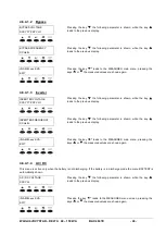
4.6.4.3.4
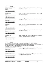
Battery Test
The BATTERY TEST cannot be started if the dip switch on the
P card in “off” position.
PRESS RESET
Pressing the key RESET the battery test is started. Pressing the key
leads to the special menu.
TO START TEST
5
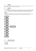
Options
5.1
Temperature Compensation
With this option the charging voltage for the battery can by regulated by means of the temperature. A sensor is placed
adjacent to the battery and connected to the rectifier of the UPS. The battery charging voltage gets reduced about
–
1mV/°C per cell, e.g. a Ups with a 192 cell battery will therefore reduce the charging voltage of about -192mV/°C. The
minus sign indicates the declination of the battery charging voltage at rising temperature.
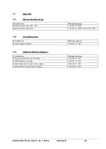
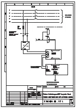
The interconnection of the temperature sensor is shown in diagram
X0013800.VP3
in annex.
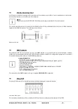
5.2
Parallel Redundant System
The parallel system can consist of up to 6 units. Each unit is equipped with an additional parallel-redundant kit (RPI-
BUS CAN) for controlling the parallel related functions.
In addition to the standard functions such as uninterruptible power supply to the load, total power control and protection
of the load from mains distortion, the parallel redundant system guarantees an uninterrupted power supply even in case
of an internal failure in one of the UPS units.
The current sharing regulation circuitry controls
the currents of the “n” units and therefore balances the currents to better
than 10%, under all load conditions. The load supplied by the inverters in parallel may have an instantaneous overload
up to “n x 200%” of the nominal load of the single unit. In case of a failure in one unit, the load is still supplied by the
other units. The load transferred to the static bypass only in case of failure of more than one unit.
i
NOTE:
For obtaining a balanced load-sharing between the single UPS-systems, it is mandatory to keep the input-
(i.e. Bypass-) lines as well as the output lines of the single units with the same length to each other and to
the distribution. In cases of extremely short length of wires, and also in cases of a very high diameter of the
cables, it is possible, that the load sharing between the single units is weak. In these cases an adjustment
at the final operating place of the units will be necessary.
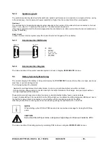
5.2.1
Additional Hardware
To transform “n” standard units into a parallel redundant system the following additional hardware is required:
“n”
RPI BUS CAN (PB110) boards (parallel redundant)
“n-1”
interconnection cable (DB9)
“n-2“
BCCON (PB123) boards
The outputs of the “n” units must be connected in parallel to the load bus bar. “n” is the number of the UPS systems in
parallel.
i
NOTE:
The standard units must be special programmed to work in parallel redundant. Please contact our service
department!