WarmFlo HE-A-**-21 Series Скачать руководство пользователя страница 7

02/04/2014 5 

NI804 

Specification Chart 


Model 

Number 

HE-A-10-21 HE-A-15-21 HE-A-20-21 


Cabinet 

Width  21” 21” 21” 

kW 

rating 

10 15 20 

Btu/h 

34000 51000 68000 

Voltage/Phase  240/1 240/1 240/1 
Circuit Breaker 

60 

1-60, 1-30 

2-60 

Amps per CB 

42 

42, 21 

42, 42 

Source 

Feed  1 2 2 

Elements 

4 6 8 

Relays 

2 4 6 

Heat CFM* 

765 (LO) 

900 (M) 

1035 (HI) 

Max. Temp. Rise 

45° F 

45° F 

45° F 

Shipping 

Weight 


*WarmFlo sensing will override this to 1200 CFM. 
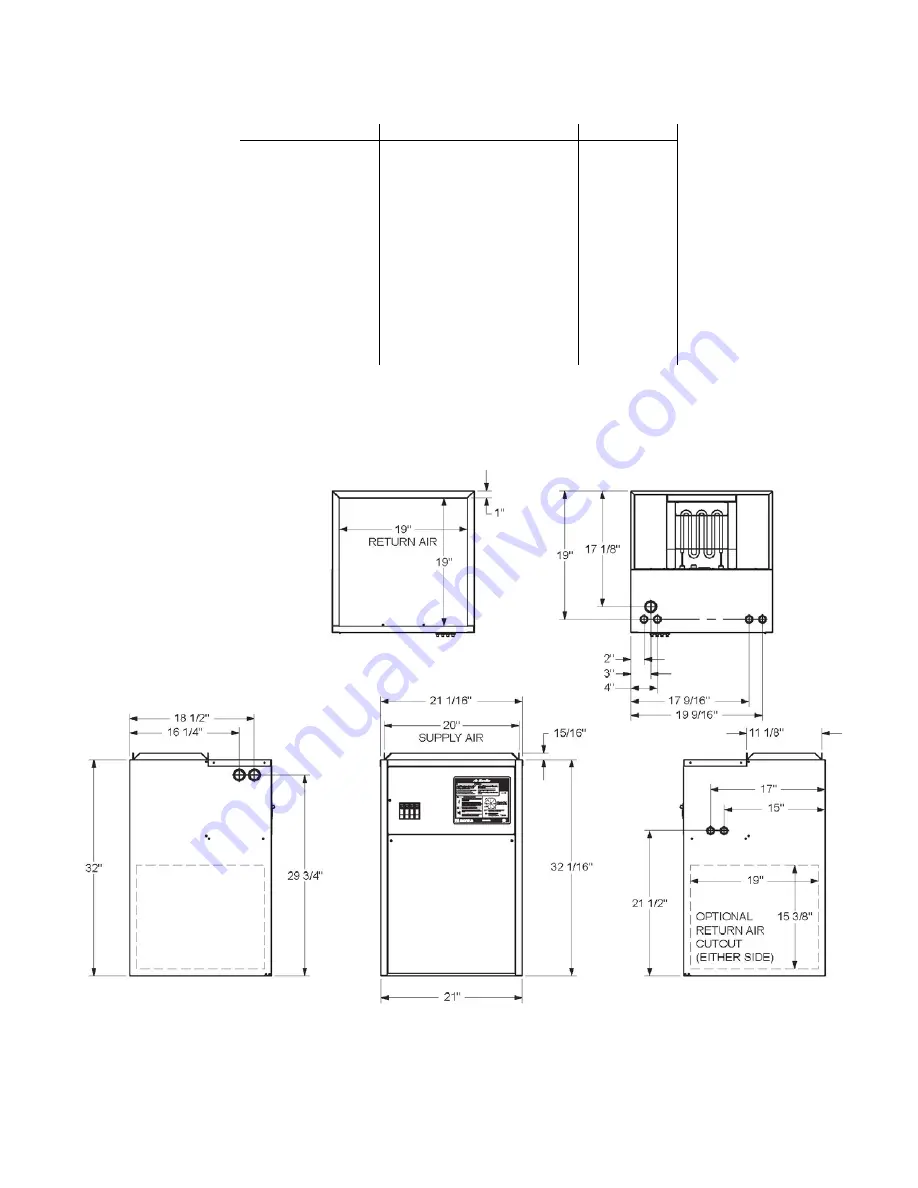
 

Product Dimensions 


Содержание HE-A-**-21 Series

Страница 1: ...te to maintain this preset temperature based on the sensing of the supply sensor ST The CFM requirement will always have to be setup for full electric capacity Heat cool conventional room thermostat a...

Страница 2: ...omments 3 Application 4 Installation Requirements 6 Mechanical Installation 7 Electrical Installation 9 Setup or Programming 11 Operation Indicators 12 Handheld Analyzer Laptop Software 13 Troubleshoo...

Страница 3: ...ion the moderate heating blower speed could be as low as 60 of full capacity and full capacity blower is only used below 30 outdoor Heat cool conventional thermostat must be used in non heat pump appl...

Страница 4: ...r bracket for slip in within the provided rails Comment The 3M MERV filter airflow resistance needs to be considered in duct design calculations Per specification information from 3M the static pressu...

Страница 5: ...es must be in the horizontal ducts after the WarmFlo duct sensor and at least 12 downstream of the WarmFlo sensor The zone controller HVAC equipment terminal block simply connects to this unit s contr...

Страница 6: ...quirements This specific model series HE A This model series is outlet warm air sensing only With a preset warm air temperature the electric elements modulate to maintain this preset temperature based...

Страница 7: ...ng 10 15 20 Btu h 34000 51000 68000 Voltage Phase 240 1 240 1 240 1 Circuit Breaker 60 1 60 1 30 2 60 Amps per CB 42 42 21 42 42 Source Feed 1 2 2 Elements 4 6 8 Relays 2 4 6 Heat CFM 765 LO 900 M 103...

Страница 8: ...fety features and controls 2 If this is a Dual Heat system this product relates only to the addition to the furnace ducting system external to the gas or oil force air furnace The owner installer assu...

Страница 9: ...circulation through a filter at this Electric Furnace inlet you may need to have a slight restriction in order for the blower motor to arrive at its setup speed All transitions must have a slope of 3...

Страница 10: ...zontal Air Conditioning Similar to upflow above the air conditioning coil is positioned at the blower outlet Depending upon the coil type and drip pan it is positioned in a field constructed plenum as...

Страница 11: ...INJURY OR DEATH WarmFlo Controller Inside View Left Board Remote Sensor Duct sensor A coil not in supply plenum the duct sensor shorter cable black wire on ST terminal is installed approximately 24 ab...

Страница 12: ...rminal The room thermostat W2 is not used or connected Outdoor Unit Air Conditioning Connect the outdoor unit 2 wires to the control board Y Y2 and C If 2 speed A C there will be a third wire connecte...

Страница 13: ...dial switch min warm air The yellow dial switch sets the operating temperature 0 30 4 62 Factory set on 3 1 38 5 80 2 46 6 88 3 54 7 96 Electric Furnace Control Inside View Right Board Room Thermostat...

Страница 14: ...lluminated when WarmFlo II is in the electric heat operating mode Utility Load Control Inside WarmFlo Board Red LED s The four red LED s next to the output connector indicate Stage 1 2 3 and 4 operati...

Страница 15: ...uh output CFM Volts x Amps x 3 4 Temperature Rise x 1 08 Sensor Temperature Calibration Both remote sensors are digital electronic and factory calibrated Normally these do not require field calibratio...

Страница 16: ...itive tool for understanding and troubleshooting the WarmFlo II controller Either test set device can display all temperatures real time evaluation of WarmFlo II functions provide temperature offsets...

Страница 17: ...ECM Motor H C and HP Stat WFPDC5632 PCB Power Sup AC to DC 5850 Motor HP ECM GE 5541 Transformer 120 240 24 40VA 4038 Triac SSR 50 amp 24VDC 5127 Relay NO 25A 277 24VDC Coil 6630 Limit O 150 O 180 25A...

Страница 18: ...J5A HEAT HI MED LO COOL D C B A CS UPCB6707 PWR ECM BLUE BLU WHT BK OUTDOOR UNIT DF W1 Y1 HEAT COOL RV LOGIC HI C RV O R Y Y2 COM VAC 24 HEAT COOL R W G Y Y2 C Y1 BK E G O ROOM THERMOSTAT HP Y 8 0 70...

Страница 19: ...HI MED LO COOL D C B A CS UPCB6707 PWR ECM BLUE BLU WHT BK OUTDOOR UNIT DF W1 Y1 HEAT COOL RV LOGIC HI C RV O R Y Y2 COM VAC 24 HEAT COOL R W G Y Y2 C Y1 BK E G O ROOM THERMOSTAT HP Y R SET JUMPER TO...

Страница 20: ......

Страница 21: ...50 F 150 F HL3 150 F HL2 150 F HL1 CB1 L2 L1 CB2 L2 L1 CB1 L1 CB1 L2 CB2 L1 CB2 L2 BK BK BK BK R R R R BK BK BK BK HECBW5844 HECBW5844 L1 L1 L1 L1 CB2 L2 CB2 L1 CB1 L2 CB1 L1 CB2 L1 CB1 L2 CB1 L1 L2 L...

Страница 22: ...EMENT HL HI LIMIT K RELAY M MOTOR BLOWER PC CIRCUIT BOARD T TAB TERMINAL SC SCREW TERMINAL L1 L1 L2 L2 CB1 L1 CB1 L2 CB2 L1 CB1 L1 CB1 L2 CB2 L1 L1 L1 L1 HECBW5844 HECBW5844 BK BK BK R R R BK BK BK CB...

Страница 23: ...5 NW823 R BR GY BL VI Y YG W BKW WBK 4 3 2 1 J2 5 6 7 8 9 10 E2 E1 150 F HL2 150 F HL1 CB1 L2 L1 CB1 L1 CB1 L2 BK BK R R BK BK HECBW5844 HECBW5844 L1 L1 CB1 L2 CB1 L1 CB1 L2 CB1 L1 L2 L2 L1 L1 COMPONE...

Страница 24: ......

Страница 25: ......

Страница 26: ...de by Electro Industries or its authorized representative Electro Industries will cover reasonable labor costs to repair defective product or product parts for ninety 90 days after installation TWENTY...

Страница 27: ...ll be null and void 4 The purchaser shall have maintained the product in accordance with the manual that accompanies the unit Annually a qualified and licensed contractor must inspect the product to a...

Отзывы: