background image

Содержание 632

Страница 1: ...WANG 3313 DIGITAL FLATBED PLOTTER 632 732A 2232A Models Customer Engineering Product Maintenance Manual 632A 729 0461 A...

Страница 2: ...ct Update Bulletins PUBs or subsequent editions This document is the property of Wang Laboratories Inc All information contained herein is considered company proprietary and its use is restricted sole...

Страница 3: ......

Страница 4: ...c lnfor1111tion contained herein is considered company proprl etary information ind its use is restricted solely to the purpose of 111lstlng you in servicing Wing products Repro duction of 111 or any...

Страница 5: ...to the X Shaft X Rack Adjustment Early Models Pinion Loading Adjustment Y Increment Adjustment Cable Tension Adjustment Photocell Adjustment Home Position Alignments Carriage Loading Adjustment Y Ann...

Страница 6: ...dure If no clamps are to be installed simply lie the plotting table on the customer 1 s table with the gearfence extending over one edge approximately three inches There are two shipping clamps on the...

Страница 7: ...the plotting surface boundaries 1 3 SOFTWARE Alphanumeric character generation is not built into the Model 32 but is provided by software This requires a 4000 byte memory minimum For this reason the M...

Страница 8: ...89 Contains the stepping motor drive decoder circuit and the reset circuit 3 6336 Insures that whatever differential distance is to be traveled by X and Y the stepping motors will be incremented at th...

Страница 9: ...d with the Model 32 some of these devices utilize the same or similar codes and will perform unnecessary functions during the operation of the Model 32 The 01 typewriter is one device that can be conn...

Страница 10: ...MODEL 08 MODEL 32 PACKAGE MODEL 23 CALCULATOR CALCULATOR MODEL 18 MODEL 01 FIGURE 2 SYSTEM CONFIGURATIONS 6 TYPEWRITER JACK MODEL 32 TABLE MODEL 32 PACKAGE MODEL 32 TABLE...

Страница 11: ...TION NOTE The following operations apply only to a Model 600 or a Model 700 720 B C calculator in a system incorporating the Model 32 4 1 PLOTTING LOCATION Plot location in the 632 is determined by th...

Страница 12: ...Pen DOWN Lowers pen if not already down and causes a movement of 0025 per integer contained in registers 01 and 00 of the 600 or the X and Y registers of the 700 The maximum number of increments that...

Страница 13: ...X Y x X Y y FIGURE 4 PLOTTING DIRECTfON 9 X Y X Y...

Страница 14: ...0 x register contains Register 00 contains 100 y register contains Keying Instructions 600 700 ALPHA 0902 WRITE ALPHA PLOT PEN DOWN 0502 PLOT PEN DOWN END ALPHA 0202 END ALPHA The pen wi 11 increment...

Страница 15: ...is given twice Figure 6 will result Keying Instructions 600 700 ALPHA 0902 WRITE ALPHA 0412 PLOT PEN DOWN 0502 PLOT PEN DOWN 0902 PLOT PEN DOWN 0502 PLOT PEN DOWN 0902 END ALPHA 0202 END ALPHA 0413 y...

Страница 16: ...gister 00 contains 100 Y register contains 100 Keying Instructions 600 700 ALPHA 0902 WRITE ALPHA 0412 PLOT PEN DOWN 0502 PLOT PEN DOWN 0902 END ALPHA 0202 END ALPHA 0413 The pen will simultaneously i...

Страница 17: ...CHANGE REGISTER VALUES X register contains 50 Y register contains 100 Keying Instructions ALPHA PLOT PEN DOWN END ALPHA 600 0902 0502 0202 WRITE ALPHA PLOT PEN DOWN END ALPHA 700 0412 0902 0413 4 4 P...

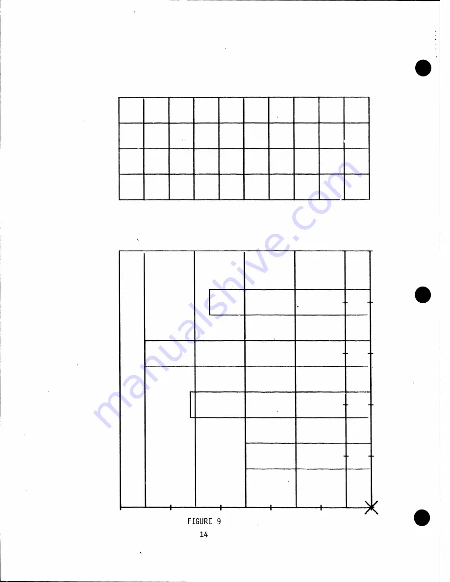
Страница 18: ...y x 50 100 FIGURE 8 CHANGING DIRECTION BETWEEN PLOT COMMANDS FIGURE 9 PLOTTER IN HOME POSITION 14...

Страница 19: ...SED FIGURE 10 HAS BEEN PROVIDED TO HELP LOCATE THESE PARTS PEN HOLUER PEN DOWN SOLENOID PRELOAD SPRING UVERTHROW ADJUSTING SCREW Pm ACTUATING ARM FIGURE 10 CARRIER MECHANISM 15 PRELOAD ADJUSTING SCREW...

Страница 20: ...TAPE AVAILABLE FOR 720 ONLY AT THIS TIME DECEMBER 1973 1 Diagnostic Tape Verify 8560 2 Dash Pot Increment Accuracy 90 Accuracy Test Program Verify 8560 5 3 PEN SOLENOID ADJUSTMENT With the pen soleno...

Страница 21: ...ADJUSTING BOLTS SOLENOID BRACKET FIGURE 11 093 015 PEN SOLENOID ADJUSTMENT OVERTRAVEL ADJUSTING SCREWS PEN MANUALLY DEPRESSED TO CONTACT TABLE TOP FIGURE 12 030 010 TABLE TOP PLUNGER OVERTRAVEL ADJUS...

Страница 22: ...p between the overtravel adjusting screw and the pen actuating arm If there is a gap with the pen carrier in the home position Step 3 and there is no gap with the pen carrier moved to the top of the t...

Страница 23: ...en solenoid energized attach a push pull scale under the pen holder raise the scale until the pen leaves the table top At this point the scale should read 5 to 5 5 oz If adjustment is necessary do so...

Страница 24: ...ARLE THE SCALE 1 1 SHOULD READ 5 5 1 2 OZ I I i i I i I I i I l r L____J I l cT 1 1 f L I l L_ 1 J SOLENOID ENERGIZED I ___ I I ___ J PEN PULLED UNTIL I IT LEAVES THE TABLE TABLE FIGURE 14 PRELOAD SPR...

Страница 25: ...___ r 1 1 l I I I i LJ I 5 7 CARRIER BRAKE ADJUSTMENT FIGURE 15 DASH POT ADJUSTMENT Run the radius program of the Model 32 see paragraph 8 2 adjust the screw until there is no noticeable line oscillat...

Страница 26: ...16 CARRIER BRAKE ADJUSTMENT 1 The distance from the bottom of the Y arm to the table surface should be uniform throughout the table within 1 16 2 Take a reading with a 611 scale at the bottom edge and...

Страница 27: ...HE YARM TO THE TABLE SURFACE SHOULD BE UNIFORM FROM THE BOTTOM OF THE TABLE TO THE TOP WITHIN 1 16 t CONNECTOR SEE NOTE l TABLE LOOSEN SCREWS r X SHAFT l Fh RACK HOLES ARE ENLARGED FOR ADJUSTMENT FIGU...

Страница 28: ...within 010 over a 30 length This is checked with a large triangle placed on a 90 plot as shown in Figure 18 The trial plot may be generated by subroutine 0014 on tape 8560 2 To adjust the Y arm loosen...

Страница 29: ...u V I D I I 11 11 J z _ Ell LOCK 69 I BOLTS cc cc J z V II n II ADJUST ARM u a TO CORRECT CCU V ANGLE II II II n 45 90 TRIANGLE TWO LINES PLOTTED AT E I II II 90 TO EACH a c c OTHER FIGURE 18 MAKING Y...

Страница 30: ...ed to the bed 2 Seat an extension block into the teeth of the two adjoining racks to be aligned See Figure 19 3 Tighten the holding screws 4 Loosen the holding screws in the third gear rack and repeat...

Страница 31: ...en adjustment is completed tighten the lock screws IOTE Some early Model 32s do not contain an adjusting screw With these units adjustment must be done by trial and error Loosen the lock screws move t...

Страница 32: ...ARM AROUND PINION BLOCK AS SHOWN PINION GEAR LOCK SCREWS TENSION BRACKET TOP VIEW AS THE BLOCK BEGINS TO r YE THE SCALE SHOULD READ 4 1 2 LBS t 1 4 LB PINION BLOCK SIDE VIEW FIGURE 20 PINION GEAR LOAD...

Страница 33: ...the carrier See Figure 23 Loosen the coils or cable looped around the drum Since expansion of the drum requires Y arm removal b it is suggested that when the drum is expanded it is expanded more than...

Страница 34: ...CORD DRUM LOCATED UNDER YPULLEY f r JACKING SCREWS FIGURE 21 CORD DRUM AND CORD DRUM LOCATION 30 CUT OUT IN DRUM ALLOWS EXPANSION AND CONTRACT ON OF CORD DRUM LOCKING SCREWS...

Страница 35: ...LOCKING SCREW ALLEN HEAD SCREW JACKING SCREW ALLEN SCRElil FIGURE 22 DRUM CROSS SECTION FIGURE 23 CORD TIGHTENING CLAMP LOCATION 31...

Страница 36: ...g of 14 oz 2 oz See Figure 24 2 The adjusting nut of the cable clamp may be turned in or out to fine ad ust the tension If the cable needs only fine adjust use the cable clamp adjusting nut If the cab...

Страница 37: ...YCORD PULLED AWA FROM ARM SCALE 14 oz 2 oz WITH CABLE PULLED 111 II PULLEY FIGURE 24 CABLE CLAMP ADJUSTING ADJUSTING HOLES COURSE ADJUSTMENT NUT FINE ADJUSTMENT CABLE TENSION ADJUSTMENTS 33...

Страница 38: ...ge See Figure 25 2 If adjustment is required position the actuator pin so that it is inside the photocell package Loosen the two locking screws holding the photocell package bracket and move the brack...

Страница 39: ...LIGNMENTS 1 The following is a procedure for aligning Y axis home position Refer to Figu es 26 27 and 28 a Turn power off X YTIMING GEARS FIGURE 26 ACTUATOR PINS HOME POSITION COMPONENT LOCATIONS 35 L...

Страница 40: ...heck alignment NOTE Due to bright lighting in some offices the photo cells may not work properly In such cases replace the motor cover before turning power back on This allows normal reset h With the...

Страница 41: ...TOP f UNTED ON TABLE YAXIS ACTUATOR Y SWl 0 YARM DURING RESET YARM TRAVELS TO LEFT MARGIN PEN CARRIER FIGURE 27 LED PHOTOCELL PACKAGE DURING RESET CARRIER TRAVELS TO LOWER MARGIN HOME POSITION ALIGNME...

Страница 42: ...FT MARGIN STOP ACTUATES LEFT LIMIT SWITCH ACTUATOR PINS ARE POSITIONED INSIDE PHOTOCELL PACKAGE FIGURE 28 ACTUATOR PINS WHILE IN HOME POSITION FIGURE 29 LEFT MARGIN STOP AND END CAP LOCATION 38 END CA...

Страница 43: ...is made by loosening the adjustment screw moving the collar to the desired location and retightening the screw 5 18 Y ARM REMOVAL AND REPLACEMENT 1 To remove the Y arm a Turn the power off on the pac...

Страница 44: ...BEARING AND ROLLER ECCENTRIC STUD ADJUSTING SCREW LOAD SPRING FIGURE 30 40 SCREW SHOULD JUST MOVE AT 2 LBS 4 OZS COLLAR ADJUSTING SCREW...

Страница 45: ...tor casting meets the outside of the X shaft This resistance may be overcome by jogging the arm up and down c Replace the stop cap on the end of the X shaft d Reinstall screw described in 5 1 1 b e Se...

Страница 46: ...djustment accomplished plot a line of 999 X 999 Y while observing the period of A to B Observe the change in the period of A to B occurring at the end of the 999 step traverse The period of A to B at...

Страница 47: ...LlJ R54 EARLY REVISION R43 R35 J 1 R54 LATEST REVISION a R43 R35 J 1 FIGURE 32 POT LOCATIONS ON LS65 PC BOARD A B l_J80 I l 1 I I A120 B FIGURE 33 __ 43...

Страница 48: ...dapter 458 0206 5 Adapter for Drafting Pen 1 Adapter 458 0204 6 Magnets 6 Plates 660 0508 6 Magnets 458 0198 7 Wrench 1 458 0221 8 Table Brackets 2 Right Hand 451 4219 2 Left Hand 451 4220 9 Screws Pa...

Страница 49: ...VEGA PEN ADAPTOR 2 The Vega pen adapter holds the Vega pen The pen is held securely in place by tightening the locknut on the adapter The adapter is screwed into the pen arm of the carrier The Lindy p...

Страница 50: ...mended is a MayLine Model 7744 There are threaded holes on the bottom of MayLine tables for mounting the table brackets The brackets are mounted on the plotter with the screws not tightened as shown i...

Страница 51: ...ed part of the program VERIFY 8560 is destroyed and must be reloaded into the calculator 8 1 CONCENTRIC CIRCLES OR ELIPSES 1 Keying order a Key loo I b Key a length of major axis c Key b length of min...

Страница 52: ...a length of major axis GO c Key b length of minor axis GO d Key 6 increment of centrical angle Example See result Figure 37 a b c d Key J Key Key Key 500 GO 500 GO 10 GO il FIGURE 37 SUBROUTINE QjJ O...

Страница 53: ...er a Key 1021 b Key a length of one side GO c Key b length of other side d Key e angle GO 2 Example See result Figure 38 a Key 1021 b Key 1000 GO c Key BOO GO d Key 30 GO GO FIGURE 38 SUBROUTINE lo2lo...

Страница 54: ...th of squares GO c Key b height of squares GO d Key N Number of squares on any side GO 2 Example See result Figure 39 a Key b Key 300 c Key 200 d Key 4 GO r GO GO N FIGURE 39 SUBROUTINE lo3IOF DIAGNOS...

Страница 55: ...l1Jlw1ll start a program to check the adjustment of the dash pot as explained in Section 5 6 8 7 To move pen in any direction less than or exceeding 999 increments and with the pen up 1 Keying order a...

Страница 56: ...EANING 1 Clean the X shaft by wiping it with a cloth or paper towel Do not moisten the towel 2 Remove any dust or foreign material from the X rail 3 Clean the X Rack and pinion gear by spraying it wit...

Страница 57: ...I...

Страница 58: ...f the Model 32A and their use Section 7 the conversion from a Model 32 to a 32A Section 10 and assembly drawings for both Models 32 and 32A Section 11 The sections in Service Bulletin 44 that are vali...

Страница 59: ...rrier Brake Adjustment 5 9 Leveling Y Arm 5 10 Squaring X Shaft 5 11 Making Y Arm Perpendicular to the X Shaft 5 12 Pinion Loading Adjustment 5 13 Y Increment Adjustment 5 14 Cable Tension Adjustment...

Страница 60: ...design eliminates warping of the table when supported incorrectly The warping caused plots to be inaccurate or in severe cases missing The carrier assembly is designed so that the pen rises and falls...

Страница 61: ...4 4 OPERATION See service Bulletin 44 5 MECHANICAL ADJUSTMENTS All mechanical adjustments for the Model 32A are contained in this section no reference to Service Bulletin 44 is required The adjust men...

Страница 62: ...z Push pull Scale Chatillon Mfg 516 500 2 5 lb x 1 oz Push pull Scale Chatillon Mfg 719 5 3 611 Scale 4 31 Scale 5 45 Triangle Pickett Mfg Ql0 30SC 12 6 Extension Block 611 Gearfence 7 Allen Wrench Se...

Страница 63: ...n housing 5 4 LOADING PROCEDURE FOR BALL PEN FIGURE 3 1 Turn locking cap to position where gr oved hole in locking cap lines up with hole in inner sleeve 2 Insert ball pen so as it bottoms on inner sl...

Страница 64: ...er is similar in adjusting the pressure and gap the point of measurement differs At the correct gap the gram reading should be as above To increase the pressure turn the adjusting screw clockwise to d...

Страница 65: ...cm gap is obtained at the solenoid plunger with solenoid deenergized pen up Measure 4 75 oz 25 downward force on the pen actuator arm at adjustment screw point Move the return spring into the correct...

Страница 66: ...e done for each pen holder 2 Pen should be adjusted just high enough to avoid hitting a paper hold down magnet 18 46 cm nominal and still be able to plot over entire area using the four corners as a q...

Страница 67: ...hs of an inch will be present on most Model 32A plotters The oscillation is more apparent at 7 83 97 173 187 263 277 and 353 The carrier brake is not always the cause of line separation or line oscill...

Страница 68: ...over 10 25 4 to within 002 005 and a maximum of 005 013 over the entire length of the rack 2 To adjust for this loosen the 6 screws directly beneath the X shaft and move the shaft to the specified po...

Страница 69: ...trial plot may be generated by subroutine 0014 on tape 8560 2 To adjust the Y arm loosen the lock bolts on the motor casting where it connects to the Y arm and shift the adjusting block by loosening...

Страница 70: ...away from the table As the block begins to move take a reading on the scale If adjustment is necessary turn the adjusting screw in to increase the tension or out to decrease tension When adjustment is...

Страница 71: ...n NOTE It is only necessary to perform Step a below when increasing the diameter of the drum To ensure uniformity when increasing or decreasing the diameter of the drum adjust both sides equally a In...

Страница 72: ...CORD DRUM LOCATED UNDER YPULLEY I Ji FIGURE 12 I JACKING SCREWS CUT OUT IN DRUM ALLOWS EXPANSION AND CONTRACTION OF CORD DRUM LOCKING SCREWS CORD DRUM AND CORD DRUM LOCATION 15...

Страница 73: ...CH1Il13THCJIT OSIO qMAJ FIGURE 13 DRUM CROSS SECTION Sl3Hlf AJ I I _____J Ii FIGURE 14 CORD TIGHTENING CLAMP LOCATION 16...

Страница 74: ...t is made reverse the procedure in 5 13 2 a to the cable then see Section 5 14 to insure proper cable tension 5 14 CABLE TENSION ADJUSTMENT 1 With the carrier assembly in the center of the Y arm using...

Страница 75: ..._ ADJUSTING HOLES COURSE ADJUSTMENT SCALE 14 oz 2 oz WITH CABLE PULLED l I I i 1 I I I I 1 I I L___ ii CABLE CLAMP I I I I 1ml F _ r IV 1 1 1 _ ADJUSTING NUT FINE ADJUSTMENT I ___ _ ______________J FI...

Страница 76: ...ge See Figure 16 2 If adjustment is required position the actuator pin so that it is inside the photocell package Loosen the two locking screws holding the photocell package bracket and move the brack...

Страница 77: ...IGNMENTS 1 The following is a procedure for aligning Y axis home position Refer to Figures 17 18 and 19 a Turn power off X YTIMING GEARS FIGURE 17 ACTUATOR PINS HOME POSITION COMPONENT LOCATIONS 20 LE...

Страница 78: ...check alignment h NOTE Due to bright lighting in some offices the photo cells may not work properly In such cases replace the motor cover before turning power back on This allows normal reset With the...

Страница 79: ...OP MOUNTED ON TABLE Yf XIS ACTUATOR Y SWl DURING RESET YARM TRAVELS TO LEFT MARGI PE CARRIER I T _I Q FIGURE 18 LED PHOTOCELL PACKAGE DURING RESET CARRIER TRAVELS TO LOWER MARGIN HOME POSITION ALIGNME...

Страница 80: ...FT MARGIN J STOP ACTUATES LEFT LIMIT SWITCH 0 ACTUATOR PINS ARE POSITIONED INSIDE PHOTOCELL PACKAGE FIGURE 19 ACTUATOR PINS WHILE IN HOME POSITION FIGURE 20 LEFT MARGIN STOP AND END CAP LOCATION 23 EN...

Страница 81: ...To remove the Y arm from the old table follow all steps in 5 17 1 except for step c Change to remove reinforcing bracket that runs the length of the Y axis at the end of table home position by removi...

Страница 82: ...e larger honeycomb table The honeycomb table can be identified by its light green plotting surface and thin construction 5 19 Y ARM ECCENTRIC See Figure 22 Located on the reverse side of the Y arm cas...

Страница 83: ...7 PL3 C3 7 Package of 5 black fiber tip pens 8 8 oz bottle blank ink MARS 747 25T 9 8 oz bottle pen cleaner MARS 746 25 10 6 magnets and plates Paper Recommendations 1 Tracing paper 100 rag vellum 2 M...

Страница 84: ...n 5 17 Remove locking nuts and tension screw from front of carrier assembly screw is connected to cable Remove end screw located at rear of carrier assembly screw is connected to cable Position the en...

Страница 85: ...The next center is 3 81 9 68 cm from the first Both centers are 56 1 42 cm from the center line of the Y arm 11 Install new carrier assembly 12 Tighten the two eccentric controlled roller bearings ag...

Страница 86: ...BEARING AND ROLLER ECCENTRIC STUD ADJUSTING SCREW LOAD SPRING FIGURE 24 29 SCREW SHOULD JUST MOVE AT 2 LBS 4 OZS COLLAR u ADJUSTING SCREW...

Страница 87: ...mplete electronic redesign of the 2232A Also note that the 2232B has a slower reset speed than the 2232A yet the plotting speed is unchanged The A and B versions of the Model 2232 differ only electron...

Страница 88: ...awings are arranged in this section DRAWING II MODEL PAGE E6403 225 32 33 E6403 223 32 34 E6403 224 sheet 1 of 2 32 35 D6403 224 sheet 2 of 2 32 36 D6403 219 32 37 C6403 222 32 38 C6403 221 32 32A 39...

Страница 89: ...19 Mount Pen Roller J l J 6403 222 Y Arm Mount Pulley Bracket J l J 6403 221 Y Arm Guide Plate J l J 6403 215 Connector J l J 6403 211 X Motor Pulley l J 6403 209 Y Motor Pulley l J 6403 212 Interrupt...

Страница 90: ...MODEL 32A ASSEMBLY DRAWINGS 1 l l ount n n n ll r otor I Pul lev CltOf I Pul lev Interrupter oduh i t I l r ln td n1t fl JI nl rn11 FIGURE 26 32...

Страница 91: ...If D c 14 II 1i II I I ij AllMI 1 11 A A _ _ _ a f j _ IC H G D 33...

Страница 92: ...I M a I c I 1 11 12 11 10 __ _____ 1 _ _ L L J 1 t t 1 14 II 12 n a_ ON I 10 rw _ S 61Z I r11 1t111r Ill h llU J a JI l llr Niii r 61 r4Hl IJ tfl 7 S i ir MN o i _ Oi i WANG zz 7 4 34 H G...

Страница 93: ...ftllf OI r Aal _ 0 WO NI tlllll l llfl 111 l INI 11r1 N r11t111 II I 1 1111 IUllWl4 C atfl llll 1 1 11 1 II 0 r11111 4 1 111 1 111rr41 J J s H I lfr t _N _U 1111 f 11 1 14 IN NIPl li P t t E K I 11111...

Страница 94: ...11 11 c B P D 111i A wo 0 111 111 I t 11 10 9 8 7 6 Nori l I 1 04 K ON llU l llhr V QI 1117 1 r N IN 11 Sllll IT z ll N 1 6 r11 r 1440 al l l lll _ r __ M 1ltr WAflifGPAUNO ITIM Ort NAM If H _ 1 I 1...

Страница 95: ...1 6 A 1 J IJll 0 1 11_ _ 1 1 0 l 1 1 c _ 7Z M n 4s1 1r16 1 h 1 1 o o 30 11 c o 7 _ 7 0 1 1 7 7 N N tt r 1 l _ 10 t O IC 0 1 t t lt _C C 1AT 1111 II 11 0J IJ4 r UC 1011 0 0 ui 1r10 t l 6 IN 6 4 C _ 1 N...

Страница 96: ...l C 1 oe e 6SC U llZ z re E N r NO 61U l7 1 12 I l N S_ t IS NT o O too II 2 S t f P IV ND t S rl llNL ISSO IV 10 4S Z ZOl7 I P Ar t S l i IT N l ZS lt _ _ fJ z 19C vAro t JZS 2 107 7 z t W rCll _J 60...

Страница 97: ..._ _ Jf_ f l ttOU llVlNO 1n _ 1 u lM n 111 r I AT T E T T I I I D 0 0100 6 660 0 I s llC 6 0 11 r I l J _ Z Z0 16 I 61 008 2 I 8 0 2 I I WANGP AATNO IT M QTV c COfJ 8 i t ProL oc r re sc rl llYLO K C...

Страница 98: ...I Alll c 11 13 n _ 40 zr I...

Страница 99: ...EW 8 FNLARGf D N T 5 SEE NOTE 1 t CNJ 1 1 t i __ t 1s 6Sl 15 7 I P N_ ot t 078 t J z o _ __ 6_1_ _3_ _o_9 ____ _ _ 1_P _ t _w _ P N o_r_ o_c _ _t t t t r c c _c __ P_JN_ _s_ _ _o _ 3_ _ s_ 9 1 t 7_8_...

Страница 100: ...y y c s 660 Oii 7 11 L OCTITE S C ecW OCK 1 660 0 06 6 Ill t ocr1rc B S ECr ON X X 6Sl 15 7 5 I P N_ K i L 078 01 11 Yz 6S6 00CJ6 I C O INNV l Vf S E e o ws 8 6 03 87 B 461 310 9 3 I Pl 6 PHOT OC L l...

Страница 101: ...6S f 0070 r c MINRL _ S P r 375 2 03 3 I INrE VPTER vfO ObL f 0088 2 I 8 1 Y _ NOTO C L L 4 58 0 39 I I HO i Pc _ PHOTO C L WANGPMTNO ITEM QTY NAME O flRH UHDON MW U 00N WANG E64D3 2JI LJ41J3 22 LABCR...

Страница 102: ...e1N 91 f NJ9 s ozoe z PVl UT 1111r1V11 1 11 oe I S N fltrr i p WANG PART NO ITIM QTY NAM 1 1U V IOOf I U U lti WANG 3 i e ltQllllATC tfa NC n a LI Al Mr1W JU a Ill UC a llM IC 41 I I IMTUl IAl IY OWN...

Страница 103: ...EY Y D WE S EG ON B 40 1 S 461 10s I t SflAFL y DRWE SEif B 6 3 15 J Ii WANG PART NO ITEM QTY NAME MATERIAL DESCRIPTION f Q 1 w O r flRST U5lDON MSYUSIOON BY DATE APP OVED DY WANG DATE I e 21s E _ OJ...

Страница 104: ...7 Z s I l N J el r 1 N Nt9 S l S 3 8 B 65 3 600 4 I WASll e NYL 01 0 B Gs 0 000 3 I C O e lNNV l V S S CE JWt 4o f05 187 z I ASS F WHEEL SEEOIV 86 90 218 46S 10 50 I I HVB P lMl E P l YE r E ONG C 6 0...

Страница 105: ...1 46 S 02 2 I 5 1 Nt A U r Y 0 0406 Z 6S l 0 I I F YWNEFL s 1 1G B 903 1 98 WANG PART NO ITEM QTY NAME MATERIAL DEICR1PT10N I a Qt1 r 1 FIRST USIDON ASSY USIDON BY DATE APPROVED BY DATE 1 WANG z 4 40...

Страница 106: ...II 11 II 10 N G G Al fli IS D c c IJ 12 II IG 9 48...

Страница 107: ...II II II 1111 1111 II II II II 11 II II II II II 11 11 II II 11 11 II II 1111 1111 1111 1111 11 II II II II II 1111 1111 II II 11 11 II II 11 11 II II 11 11 1111 1111 II II 11 II 1111 1111 II II 11 11...

Страница 108: ...11 11 N G D c C j l r c l IEJ V C rn Ulf nEN A R l t l l L J I t 4 t l I _ t __...

Страница 109: ...1 11 10 10 9 9 I l 0 I I j o ti 8 8 7 6 P D 7 6 5 3 0 r Ot 0 N Iii St lllNI l IPrQI r1 i11Tll 1 SNllr IZ nr ON 1 11 r 1 _ 6 S Ji lt C I 5 WANGP RlNO ITIM QTY AM _ _ f TU IOC a tl l V ION 1 1 lWANG r T...

Страница 110: ..._ 6 C 0 i 4 X _ c cl S caon t S _ ____ l l 005 3 f D9YJ___ _ _o I I Lt W l uf N r 11 1 It A I 18 t I J l l t ff 3 J l f t _ 1 111 J I C r _ 1d I t A d f R u I H NUI 1 ll Jl I ur t 11 111 I llUI I 11...

Страница 111: ...O z sc eFr J I 6 c NZ4 3 w 1c sc e n i 1 5 1a97 1 P llr iw11 11 3i S s e ic r cc _ z 4 z_ __ ____ i3 s 1 rc h ____ __ ___ _ ____ IP q_ tP_ O _ UOl I llGfNO 09 IUID DI f MC D HOll ftlf _U 11 11 OtA OIU...

Страница 112: ...U l t ltl H 0 o u_ z tT SC I ttJ I 1f1 AP 10 lO M ll_l_ 1 tOr f t J_ 1 o 1 fJ t Ufi I HP fM 171 OHi 1 11 i 1 1111 It_ _ _ I 11914 I i Ar I I 111 ilfllJ I 1 IJ ll l11 1 i11 _r 1 llV ll y 11 1 I i r r I...

Страница 113: ..._ c l 1 7 i l I t i l t o1 f r z t I J c_ ii _0 Ec 1 r AT IHM l fY NA Ml Mo rn11 L Jl i fl l i f4 li Tl t v11Jr 1u nv 1 1 rJ I J tut M A J _ _ _ _ _ _ _ _ _ _ _ _ _ rWANG MAflAIAl M J 1ll N J I CONUO...

Страница 114: ...4 _ 0 I I fll K T flDT cRiw SEE DWG 17 28 WANG PART NO ITEM QTY NAME MATERIAL D ICRIPT10N I Q Ql0 rlRST U5 00N AS Y USfOON BY DATE APPROVED BY DATE 11 1 WANG LABORATOR WC OWN Arr1 c r 7 4 E fNGR J_ J...

Страница 115: ..._ _ J D c II 10 6 IJtll IU eo 1 __ __ I I r I I E 1 0...

Страница 116: ...I JI 00 E D c I I B J I i 1 I I B t r r I 1 1 ll fl Al 1 1 Wf _ _ Lr l 0Wt4 l LK I t 11 re I IP 0 1 c t v 1 ll ll4 _ I OI I Al o llH II Pl 3...

Страница 117: ...VI ID 0 c II IO 7 s cot1 1 l 0 0...

Страница 118: ......

Страница 119: ...ments d STORE RIGHT e Key f x 00 Pen moves to the position entered 1 2 PEN DOWN By keying f x the plotter plots to the position keyed in the left and right registers NOTICE This document is the proper...

Страница 120: ...lotter draws a circle with the given radius and incrementing angle The pen must be moved to the desired plotting area before plotting the circle Keying Order a Key f x Display is blanked b Enter the l...

Страница 121: ...ng area Keying Order a Key f x lo3j Display is blanked b Enter the length of the radius GO Display blanks c Enter the incrementing angle in degrees GO EXAMPLE See Figure 2 a Key f x b Key 500 GO c Key...

Страница 122: ...GO Display blanks d Key number of rectangles on each side GO N EXAMPLE See Figure 3 a Key f x 11 b Key 300 GO c Key 200 GO d Key 4 GO N a 300 75 1 9 cm b 200 5II 1 3 cm N 4 4 RECTANGLES 1 7 DASH POT...

Страница 123: ...OM is bad All plotting output figures shown are actual size EQUIPMENT NEEDED 600 14 632 Digital Flatbed Plotter 632 Alpha User ROM 2 1 OPERATING INSTRUCTIONS BLOCK 1 12131 a Plug user ROM into the 600...

Страница 124: ...632 ALPHA ROM DIAGNOSTIC E FJ K QUV XY Z 0 7 8 I J 0 r r r n r v h cs I p r 11 r Y vJ 7 T 7 v 7 J_ l7 7...

Страница 125: ...after keying GO 2 1 indicates PROM 2 will be tested after keying GO 34 1 indicates PROMs 3 and 4 will be tested after keying GO See Figure 5 for the numbering of the PROMs for the purpose of this diag...

Страница 126: ...ONE 24 Key GO 2 1 NONE 25 Key GO 3 1 NONE 26 Key GO 3 1 NONE 27 Key GO 1 NONE 28 Key GO 2 NONE 29 Key GO 3 1 NONE 30 Key GO 34 1 NONE 31 Key GO 0 NONE 32 Key GO 5 NONE 33 Key GO 149 NONE 34 Key GO 294...

Страница 127: ...RESULT To test PROM tfl 1 Key SEARCH 1 1 1 2 Key GO 2 1 3 Key GO 1 1 4 Key GO 2 1 5 Key GO 1 1 6 Key GO 99999 0 Pl through P20 are identified in APPENDIX A z s FIGURE 6 9 PLOT NONE Pl P2 P3 P4 PS Fin...

Страница 128: ...6 Key GO S678 l PS 7 Key GO 2 1 P6 8 Key GO 23 1 P7 9 Key GO 99999 0 PB Final output must Fig 7 To test PROM 113 1 Key SEARCH 3 1 1 NONE 2 Key GO 2 1 Pl 3 Key GO 1 1 P2 4 Key GO 3 1 P3 s Key GO 2 1 P...

Страница 129: ...WANG 632cl...

Страница 130: ...Ci c N CX 632ul ABCDE EFGHIJKLMNOPQRSTUV V XYZ 012345618 89 up 9 66ppO...

Страница 131: ...3 s Key GO 4 1 P9 6 Key GO 4 1 Pl2 7 Key GO 4 1 Pl3 8 Key GO 45 1 Pl4 9 Key GO 99999 0 Pl5 Final output must Fig 9 To test PROM 5 1 Key SEARCH 5 1 1 NONE 2 Key GO 2 1 Pl 3 Key GO 1 1 P2 4 Key GO 2 1 P...

Страница 132: ...I T I T FIGURE 9 14 L _ T I I I 7...

Страница 133: ...N To test PROM 6 1 Key SEARCH 6 2 Key GO 3 Key GO 4 Key GO 5 Key GO 6 Key GO 7 Key GO w 0 _ co FIGURE 10 DISPLAY RESULT PLOT 1 1 NONE 2 1 Pl 1 1 P2 2 1 P3 1 1 P4 5678 1 PS 99999 0 PlB Final outpu must...

Страница 134: ...Ci I c 0 1 11 __ __ EFGHIJKLMNOPQRSTUV _I...

Страница 135: ...l 3 Key GO 1 1 P2 4 Key GO 2 1 P3 s Key GO 1 1 P4 6 Key GO S678 l PS 7 Key GO 99999 0 Pl9 Final output must Fig 12 To test PROM f8 1 Key SEARCH 8 1 1 NONE 2 Key GO 2 1 Pl 3 Key GO 1 1 P2 4 Key GO 2 1...

Страница 136: ...WANG 00 V XYZ 012345578...

Страница 137: ...WANG 0 tJ IT1 w...

Страница 138: ...WANG above the 5 x 5 square P8 Plot 632 1 beside P7 P9 Plot which intersects with Pl at origin PlO Plot a square inside the 5 x 5 box Pll Plot a straight line inside the small square Pl2 Plot the XY a...

Страница 139: ......

Отзывы:

Похожие инструкции для 632