WALTHERS
®
!!!!
REMOVE CENTER
REMOVE CENTER
REMOVE CENTER
REMOVE CENTER
JUMPER FOR NORMAL
JUMPER FOR NORMAL
JUMPER FOR NORMAL
JUMPER FOR NORMAL
OPERATION
OPERATION
OPERATION
OPERATION
USE 942
USE 942
USE 942
USE 942----113 EXTENSION CABLES (UP TO 4) TO EXTEND
113 EXTENSION CABLES (UP TO 4) TO EXTEND
113 EXTENSION CABLES (UP TO 4) TO EXTEND
113 EXTENSION CABLES (UP TO 4) TO EXTEND
POWER AND FASCIA CONNECTIONS AS NEEDED
POWER AND FASCIA CONNECTIONS AS NEEDED
POWER AND FASCIA CONNECTIONS AS NEEDED
POWER AND FASCIA CONNECTIONS AS NEEDED
For complete details on mounting, electrical connections, switch machine adjustments,
For complete details on mounting, electrical connections, switch machine adjustments,
For complete details on mounting, electrical connections, switch machine adjustments,
For complete details on mounting, electrical connections, switch machine adjustments,
options and warranty information, see the Switch Machine Reference Guide at
options and warranty information, see the Switch Machine Reference Guide at
options and warranty information, see the Switch Machine Reference Guide at
options and warranty information, see the Switch Machine Reference Guide at
walthers.com/products/walthers
walthers.com/products/walthers
walthers.com/products/walthers
walthers.com/products/walthers----control
control
control
control----system
system
system
system....
(continued from other side)
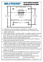
9) With switch machine in center position, insert actuator wire though subroadbed and
up thru the center hole in the throwbar. Center the machine, align with template
and secure with screws supplied.
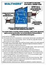
10) With power off, connect power input and fascia control cables to the switch machine
as shown. Remove the center jumper. See Switch Machine Reference Guide for
complete information on electrical connections.
11) Remove the centering yoke from the turnout and apply power. Switch machine will
stay at center on first power up after center jumper is removed.
12) Use the fascia control to cycle the switch machine from Normal to Reverse.
13) Check turnout points for proper travel and holding tension. Adjust output arm as
detailed in the Switch Machine Reference Guide if required. The actuator travel is
infinitely adjustable from 2 mm to 13 mm (1/16” to 1/2“) to accommodate a wide
variety of scales, turnouts, and roadbed dimensions.
14) When satisfied with switch machine operation, finish the turnout mounting. Wear
proper eye protection and remove any excess actuator wire above the throwbar
with a cut-off disk or hard wire cutting pliers.
15) Make electrical connections to aux switches as desired to complete installation.
CONNECT INPUT POWER
CONNECT INPUT POWER
CONNECT INPUT POWER
CONNECT INPUT POWER
FROM 942
FROM 942
FROM 942
FROM 942----111
111
111
111
DISTRIBUTION BLOCK
DISTRIBUTION BLOCK
DISTRIBUTION BLOCK
DISTRIBUTION BLOCK
942
942
942
942----101 SWITCH MACHINE
101 SWITCH MACHINE
101 SWITCH MACHINE
101 SWITCH MACHINE
ELECTRICAL CONNECTIONS
ELECTRICAL CONNECTIONS
ELECTRICAL CONNECTIONS
ELECTRICAL CONNECTIONS
CONNECT 942
CONNECT 942
CONNECT 942
CONNECT 942----121,
121,
121,
121,
942
942
942
942----122, or 942
122, or 942
122, or 942
122, or 942----123
123
123
123
FASCIA CONTROLLERS
FASCIA CONTROLLERS
FASCIA CONTROLLERS
FASCIA CONTROLLERS
TO STD INPUT
TO STD INPUT
TO STD INPUT
TO STD INPUT


