Walter Wilson OLR112A16A Скачать руководство пользователя страница 33


8


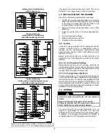
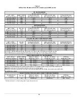
BLOWER SPEED ADJUSTMENTS  

(A/C MODE, 4 SPEED MOTOR) 


A/C CAPACITY 

(TONS) 

RECOMMENDED 
BLOWER SPEED 

2.5 

MED-LOW 

3.0 

MED-HIGH 

4.0 

HIGH 


To effect the adjustment, the RED (for heating) and BLUE (for 
cooling and heat pump) wires can be changed on the motor. 
Also, refer to the position of the wires on the electronic board 
of the unit and consult the wiring diagrams. If the heating and 
air conditioning speeds are the same, the RED wire must be 
moved to “UNUSED LEADS” on the electronic board and the 
jumper provided with the BLUE wire must be used between the 
“HEAT” and “COOL” terminals. 


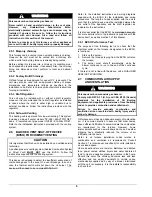
The blower start/stop delays can be adjusted by positioning the 
DIP switches on the electronic board as shown in the following 
figures. However, the recommended adjustments are 60 
seconds blower ON delay and 2 minutes blower OFF delay. 

Blower “OFF” delay 

Board # ST9103A 


Blower start / stop delays 

Board # 1158 


2.11 SUPPLY


AIR


ADJUSTMENTS


(ECM


VARIABLE


SPEED


MOTORS) 

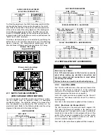
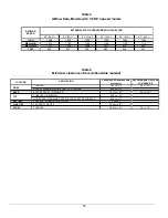
On units equipped with ECM variable speed blower motors, 
the air supply must be adjusted based on heating/air 
conditioning output. The start/stop delays of the blower must 
also be adjusted by positioning the DIP switches on the 
electronic board. Refer to the following tables and the wiring 
diagram in this manual for the proper settings: 


HEATING MODE 


SW1 – HEAT  

DIP Switch Positions 

1 2 

POSITION 

Input 

USGPH 

OFF OFF 

0.68 

ON OFF 

0.80 

OFF ON 

C* 

0.68 

ON ON  D* 

0.80 

   * Alternate adjustment for a higher air temperature rise. 


AIR CONDITIONING MODE  


SW2 – COOL  

DIP Switch Positions 

1 2 

POSITION 

Output 

Tons 

OFF OFF 

4.0 

ON OFF 

3.5 

OFF ON 

3.0 

ON ON 

2.5 


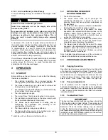
CFM ADJUSTMENTS – ALL MODES 


SW3 – ADJ (Adjustment) 

DIP Switch Positions 

1 2 

POSITION 

CFM HTG.   

%  increase  

or decrease


CFM A/C  

%  increase  

or decrease


OFF OFF 

0% 

0% 

ON OFF 

+10% 

+10% 

OFF ON 

-10% 

-10% 

ON ON 

N/A 

0% 


DELAY ADJUSTMENTS – HEATING MODE  


SW4 – Delay 

DIP Switch Positions 

1 2 

POSITION 

Input 

USGPH 

OFF OFF 

0.68 

ON OFF 

0.80 

OFF ON 

C* 

ALL 

ON ON  D* 

ALL 

   * Alternate adjustments for both input rate (refer to air flow table). 

2.12 INSTALLATION


OF


ACCESSORIES 


WARNING 


Electrical shock hazard. 


Turn OFF electrical power at the fuse box or service 
panel before making any electrical connections and 
ensure a proper ground connection is made before 
connecting line voltage.  


Failure to do so can result in death or bodily injury. 


2.12.1 Humidifier 

(HUM) 

The 120 VAC HUM terminal on the electronic board of the 
blower is tied directly to terminal 8 of the 9-terminal 
connector of the electronic board. It supplies 120 VAC 
electric power when the burner is in operation. 


A 24 VAC signal can also be supplied from the W and C 
terminals on the blower electronic board to activate a 
switching relay.  


Also refer to the instructions supplied with the accessory. 

2.12.2  Electronic Air Cleaner (EAC)  

The EAC terminal on the electronic board supplies 120 
VAC when the blower is operating in the heating or air 
conditioning mode. This signal can be used to activate an 
electronic air cleaner that is not equipped with an air flow 
switch. If the cleaner is equipped with an air flow switch, 
the S terminal on the electronic board can be used to 
provide a constant supply of 120 VAC. 


Also refer to the instructions supplied with the accessory. 

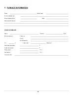
Содержание OLR112A16A

Страница 1: ...ILISER LES RENSEIGNEMENTS DANS CE MANUEL POUR L INSTALLATION ENTRETIEN DE L APPAREIL ET GARDER LE DOCUMENT PR S DE L UNIT POUR R F RENCES ULT RIEURES PROPRI TAIRE S V P GARDER CE MANUEL PR S DE L UNIT...

Страница 2: ...MISE EN MARCHE 10 3 2 S QUENCE DE FONCTIONNEMENT EN MODE CHAUFFAGE AU MAZOUT 10 3 3 V RIFICATIONS ET AJUSTEMENTS 11 4 ENTRETIEN 12 4 1 NETTOYAGE DE L CHANGEUR DE CHALEUR 12 4 2 NETTOYAGE DU DISPOSITI...

Страница 3: ...e iv Le filtre air comment le changer v rifier mensuellement et nettoyer ou changer si n cessaire g Avant d appeler pour le service prendre en note les renseignements sur la page 14 de ce manuel pour...

Страница 4: ...it Seule l dition la plus r cente des codes doit tre utilis e 2 1 EMPLACEMENT MISE EN GARDE Risque d incendie ou d explosion L appareil doit tre install au niveau Ne jamais installer avec une inclinai...

Страница 5: ...ircuit devrait tre utilis entre le panneau lectrique principal et l unit Utiliser uniquement du fil de cuivre pour du courant de 115V avec cette unit Si vous remplacez des fils d origine de l appareil...

Страница 6: ...es Se r f rer au manuel d instruction et marquages du contr le du br leur pour plus de d tail concernant l ajustement du d lai post purge 2 5 VACUATION MISE EN GARDE Risque d empoisonnement par monoxy...

Страница 7: ...nt n est pas conforme APPELER UN TECHNICIEN QUALIFI 2 7 APPROVISIONNEMENT EN AIR DE COMBUSTION ET VENTILATION MISE EN GARDE Risque d empoisonnement par monoxyde de carbone R f rer aux codes d installa...

Страница 8: ...raccordement au br leur Le conduit de mazout doit tre prot g pour viter un dommage celui ci Les installations ayant un r servoir de mazout situ sous le niveau du br leur doivent utiliser une ligne de...

Страница 9: ...ventilateur Carte 1158 2 11 AJUSTEMENT DES D BITS D AIR DE VENTILATION MOTEUR VITESSE VARIABLE ECM Sur les unit s quip s d un moteur de ventilateur vitesse variable de type ECM il faut v rifier que l...

Страница 10: ...fournaise et de la thermopompe Il pr vient aussi la transition directe du mode de chauffage thermopompe au mode de chauffage au mazout R f rer aux instructions du thermostat ou du contr le pour un bra...

Страница 11: ...n 18 pouces de la bride d vacuation de la fournaise Pour les installations avec une vacuation murale utiliser l orifice pr vu cet effet 2 Suite un d part froid laisser fonctionner l unit environ 5 min...

Страница 12: ...s de mazout accumul des vapeurs de mazout ou que la chambre combustion est tr s chaude 4 ENTRETIEN MISE EN GARDE Risque de d charge lectrique Avant d effectuer des travaux d entretien FERMER l aliment...

Страница 13: ...r thermique endommag doit tre remplac 6 Nettoyer et enlever toute accumulation de salet ou obstruction de l int rieur du tube de transfert de chaleur 7 Remonter verrouiller et fixer le bo tier de comm...

Страница 14: ...se du technicien de service R SULTAT DU TEST DE MISE EN MARCHE Gicleur Pression lb po 2 Ajustements du br leur Bande principale Bande fine Position de la t te CO2 Indice de fum e Bacharach Temp rature...

Страница 15: ...IELLO MOD LE 40 BF5 vacuation directe DV Longueur d insertion du tube du br leur pouces Gicleur Delavan 0 60 70A 0 70 70A 0 60 70A 0 70 70A Pression de la pompe minimum et maximum PSIG 130 160 130 160...

Страница 16: ...rtRun D lai On Niveau PCM Temps D lai Off Niveau PCM Temps A 1 OFF 2 OFF 0 68 13 45 sec 19 60 sec 38 3 min B 1 ON 2 OFF 0 80 13 45 sec 19 30 sec 38 3 min C 1 OFF 2 ON All 13 45 sec 100 0 sec 100 2 min...

Страница 17: ...N STATIQUE EXTERNE AVEC FILTRE AIR EMPLACEMENT APPLICATION D GAGEMENTS mat riaux combustibles ACC S RECOMMAND POUR L ENTRETIEN FOURNAISE 2 54 cm 1 0 6 m 24 PL NUM D ALIMENTATION JUSQU 1 8m 6 DE LA FOU...

Страница 18: ...18 Figure 2 Dimensions de la fournaise...

Страница 19: ...19 Figure 3 Diagramme lectrique Moteur 4 vitesses PSC...

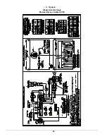
Страница 20: ...20 Figure 4 Diagramme lectrique Moteur vitesse variable ECM...

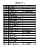
Страница 21: ...21 COMPOSANTES ET PI CES DE REMPLACEMENT...

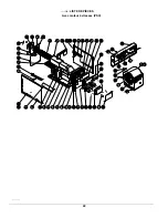
Страница 22: ...22 LISTE DE PI CES Avec moteur 4 vitesses PSC B50093B...

Страница 23: ...E DROIT 26 B03711 01 SUPPORT FILTRE ANGLE DROIT 27 B03553 ESPACEUR DE BOITE ELECTRIQUE 28 B03549 BOITE ELECTRIQUE 29 R02R003 CONTR LE HAUTE LIMITE L195 30 1 75 po 30 B03550 COUVERCLE BOITE ELECTRIQUE...

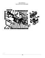
Страница 24: ...24 LISTE DE PI CES Avec moteur vitesse variable ECM B50094B...

Страница 25: ...14 01 ISOLATION PANNEAU DE COTE DROIT 26 B03711 01 SUPPORT FILTRE ANGLE DROIT 27 B03553 ESPACEUR DE BOITE ELECTRIQUE 28 B03534 BOITE ELECTRIQUE 29 R02R003 CONTR LE HAUTE LIMITE L95 30F 1 75 po 30 B035...

Страница 26: ...CIAN USE THE INFORMATION IN THIS MANUAL FOR THE INSTALLATION SERVICING OF THE FURNACE AND KEEP THE DOCUMENT NEAR THE UNIT FOR FUTURE REFERENCE HOMEOWNER PLEASE KEEP THIS MANUAL NEAR THE FURNACE FOR FU...

Страница 27: ...OPERATION 9 3 1 START UP 9 3 2 OPERATING SEQUENCE OIL HEATING MODE 9 3 3 CHECKS AND ADJUSTMENTS 9 4 MAINTENANCE 11 4 1 CLEANING THE HEAT EXCHANGER 11 4 2 CLEANING THE BLOCKED VENT SHUT OFF DEVICE BVS...

Страница 28: ...formation such as the model and serial numbers of the furnace WARNING Installations and repairs performed by unqualified persons can result in hazards to them and to others Installations must conform...

Страница 29: ...ea where the ambient and return air temperatures are above 15 C 60 F In addition the furnace should be installed as closely as possible to the vent so that the connections are direct and kept to a min...

Страница 30: ...able 1 and based on a pump pressure of 100 psi Always select nozzle sizes by working back from the desired flow rate at operating pressure and not the nozzle marking 2 4 2 Air and Turbulator Settings...

Страница 31: ...l switch will shut down the oil burner The device will then need to be re armed MANUALLY Refer to the detailed instructions and wiring diagrams supplied with the BVSO for the installation and wiring p...

Страница 32: ...s Ensure that the tank is full of clean oil Use No 1 or No 2 Heating Oil ASTM D396 U S or in Canada use No 1 or No 2 Furnace Oil A manual shut off valve and an oil filter shall be installed in sequenc...

Страница 33: ...Positions 1 2 POSITION Output Tons OFF OFF A 4 0 ON OFF B 3 5 OFF ON C 3 0 ON ON D 2 5 CFM ADJUSTMENTS ALL MODES SW3 ADJ Adjustment DIP Switch Positions 1 2 POSITION CFM HTG increase or decrease CFM...

Страница 34: ...the unit turn the main electrical switch on 3 2 OPERATING SEQUENCE OIL HEATING MODE 1 The W R contact closes 2 The burner motor starts up to pre purge the combustion chamber for a period of 10 to 15 s...

Страница 35: ...xcessive combustion air due to the air band being too wide open or a lack of flue draft chimney effect or some other blockage such as soot in the secondary section of the heat exchanger or the use of...

Страница 36: ...bling the unit the heat exchanger and combustion chamber should be inspected to determine if replacement is required 9 After the cleaning replace the heat exchanger baffles flue collar plate and oil b...

Страница 37: ...vice telephone Day Night Dealer name and address START UP RESULTS Nozzle Pressure lb po 2 Burner adjustments Primary air Fine air Drawer Assembly CO2 Smoke scale Bacharach Gross stack temperature F Am...

Страница 38: ...vent DV Burner tube insertion length inches Nozzle Delavan 0 60 70A 0 70 70A 0 60 70A 0 70 70A Minimum and Maximum pump pressure PSIG 130 to 160 130 to 160 130 to 160 130 to 160 Combustion air adjust...

Страница 39: ...e ShortRun On Delay CFM Level Time Off Delay CFM Level Time A 1 OFF 2 OFF 0 68 13 45 sec 19 60 sec 38 3 min B 1 ON 2 OFF 0 80 13 45 sec 19 30 sec 38 3 min C 1 OFF 2 ON All 13 45 sec 100 0 sec 100 2 mi...

Страница 40: ...890 860 830 BLOWER SPEED EXTERNAL STATIC PRESSURE WITH AIR FILTER LOCATION CLEARANCES combustible materials RECOMMANDED ACCESS FOR SERVICE FURNACE 2 54 cm 1 0 6 m 24 SUPPLY PLENUM WITHIN 6 FEET OF FUR...

Страница 41: ...16 Figure 2 Furnace dimensions...

Страница 42: ...17 Figure 3 Wiring Diagram 4 Speed Motor PSC...

Страница 43: ...18 Figure 4 Wiring Diagram Variable Speed Motor ECM...

Страница 44: ...19 COMPONENTS AND REPLACEMENT PARTS...

Страница 45: ...20 PARTS LIST With 4 speed motor PSC B50093B...

Страница 46: ...HT SIDE PANEL INSULATION 26 B03711 01 RIGHT ANGLE FILTER RACK 27 B03553 ELECTRICAL BOX SPACER 28 B03549 ELECTRICAL BOX 29 R02R003 HIGH LIMIT L195 30F 1 75 in 30 B03550 ELECTRICAL BOX COVER Panel only...

Страница 47: ...22 PARTS LIST With variable speed motor ECM B50094B...

Страница 48: ...and baffle included 25 B03714 01 RIGHT SIDE PANEL INSULATION 26 B03711 01 RIGHT ANGLE FILTER RACK 27 B03553 ELECTRICAL BOX SPACER 28 B03534 ELECTRICAL BOX 29 R02R003 HIGH LIMIT L195 30F 1 75 in 30 B03...

Отзывы: