background image

15

3  SAFETY SIGNS

1. 

Keep safety signs clean and legible at all times, 

2. 

Replace safety signs that are missing or have become illegible.

3. 

Replaced parts that displayed a safety sign should also display the current sign.

4. 

Safety signs in Section 3 each have a part number displayed with it.  Use this part number when 

ordering replacement parts.

5. 

Safety signs are available from your authorized Distributor or Dealer Parts Department or the factory.

Z94120

Z94117

Caution: 

keep hands and feet out of inlet 

and discharge openings while machine is 

operating to avoid serious personal injury. 

Wait for all moving parts to come to a com

-

plete stop before clearing obstructions .

Caution: 

machine is extremely 

loud in operation. Hearing pro

-

tection is required or permanent 

damage will occur. Lwa is sound 

power level, Leq is the average 

sound level. 

Caution: 

flying objects, be aware of and 

Stay clear of material discharge chute, 

machine can expel wood chips fast 

enough to cause injury.

Do not point discharge at people, animals 

or buildings.  

Z94119

Caution: 

read and understand ALL 

safety and operating instructions

 in the 

manual, read and understand ALL 

safety 

labels

 located on the machine. The most 

important safety device on this equipment 

is an informed SAFE operator.  

3�2  SAFETY SIGN EXPLANATIONS:

3�1  HOW TO INSTALL SAFETY SIGNS:

• 

Be sure that the installation area is clean and dry.

• 

Be sure temperature is above 50°F (10°C).

• 

Determine exact position before you remove the backing paper.

• 

Remove the smallest portion of the split backing paper.

• 

Align the sign over the specified area and carefully press the small portion with the exposed sticky 

backing in place.

• 

Slowly peel back the remaining paper and carefully smooth the remaining portion of the sign in place.

• 

Small air pockets can be pierced with a pin and smoothed out using the piece of sign backing paper

Caution: 

Maximum size of material for 

the chipper is 75 mm (3.0"). Attempting 

to chip anything larger could stall the 

engine, damage the chipper or cause 

personal injury.

Caution:

 rotating parts are exposed or 

under a guard, do not attempt to reach 

in while parts are turning. Keep hands, 

loose clothing, and long hair away. Seri

-

ous injury will result. 

Z94120

Z94117

75mm

3.0”

Z94232

Z94203

Z94127

Z94232

Z94127

Z94204

Caution: 

Personal Protection 

Equipment (PPE) is required 

when operating this machine. 

Failure to wear PPE will result in 

personal injury

Z94116

Caution: 

Do not operate machine with

-

out shields in place, failure to do so may 

cause serious injury or death  Replace 

the shield before operating equipment.

Z94201

19mm

0.75”

Z94201

Caution: 

Maximum size of material for 

the shredder is 19 mm (0.75"). Attempt

-

ing to shred anything larger could stall 

the engine, damage the machine or 

cause personal injury.

Содержание BXMC34B

Страница 1: ...nt com PRINTED IN CANADA REV 201216 PART NUMBER Z97113 Keep this manual with the machine at all times Do not attempt to start or operate the equipment without thoroughly reviewing this manual for safe...

Страница 2: ...ECKLIST 19 4 5 CONTROLS 20 4 5 1 ENGINE BXMC34 SERIES 20 4 5 2 SHREDDER FEED 21 4 5 3 FEED CHUTE GRAB HANDLES 21 4 5 4 DRIVE ENGAGE HANDLE 22 4 6 MACHINE SET UP 22 4 7 FIELD OPERATION 23 4 7 1 PREPARE...

Страница 3: ...r service contact your local engine dealer Under no circumstances will the manufacturer be liable for any consequential damage or expense of any kind including loss of profits The manufacturer is unde...

Страница 4: ...ls _________________________________________ Dealer s Rep Signature __________ __________ __________ Delivery Date The product manuals have been received by me and I have been thoroughly instructed as...

Страница 5: ...ur and generally rectangular with single or multiple symbols The label illustrates requirements for safe operation safety equipment housekeeping etc These labels are accompanied by detailed instruc ti...

Страница 6: ...vely and quickly shreds up material The chipper portion of the BXMC features an 9cm x 13cm 3 5 x 5 angled chipper hopper that delivers wood material up to 75mm 3 0 diameter into the 2 bladed rotor for...

Страница 7: ...inently hazardous situation that if not avoided will result in death or serious injury This signal word is to be limited to the most extreme situations typically for machine components which for funct...

Страница 8: ...d safety instructions to operate the machine An untrained opera tor is not qualified and exposes himself and bystanders to possible serious injury or death It is the owners responsibility to the opera...

Страница 9: ...nderstanding of the safety precautions and of how it works Review the safety instructions with all users annually 6 This equipment is dangerous to children and persons unfamiliar with its operation Th...

Страница 10: ...cable turn fuel valve off block chock the wheels 5 Know your controls and how to stop the machine quickly in an emergency Read this manual and the one provided with the engine 6 Train all new personn...

Страница 11: ...just ed and in good operating condition 7 Ensure that all safety shielding and safety signs are properly installed and in good condi tion 2 7 MAINTENANCE SAFETY 1 Good maintenance is your responsibili...

Страница 12: ...nstallation operation main tenance repairing unplugging or moving 8 Before servicing adjusting repairing or unplugging perform the safe condition procedure disengage the drive shut off the engine ensu...

Страница 13: ...ine is flooded crank until engine starts 15 DO NOT strike flywheel with a hard object or metal tool as this may cause flywheel to shatter in operation Use proper tools to service engine 16 DO NOT oper...

Страница 14: ...Chipper Shredder until such information has been reviewed Annually review this information before the season start up Make these periodic reviews of SAFETY and OPERATION a standard practice for all of...

Страница 15: ...N EXPLANATIONS 3 1 HOW TO INSTALL SAFETY SIGNS Be sure that the installation area is clean and dry Be sure temperature is above 50 F 10 C Determine exact position before you remove the backing paper R...

Страница 16: ...lly apply to both models Good safety requires that you familiarize yourself with the various safety signs the type of warning and the area or particular function related to that area that requires you...

Страница 17: ...eed hopper open ings when the engine is running Install and secure access covers before starting engine Do not move or transport chipper when the rotor is turning Do not exceed a safe travel speed whe...

Страница 18: ...small gas engine on the frame provides power to the rotor through a V belt drive system Abraking clutch on the engine stops the rotor when the drive is disengaged PRINCIPLE COMPONENTS Lower Rotor Hou...

Страница 19: ...er Shredder requires that each operator reads and understands the using procedures and all related safety precautions outlined in this section A preoperational checklist is provided for the operator I...

Страница 20: ...the electrical system ON and the engine will run Turn the switch counterclockwise to stop the engine Fuel Shut Off Valve This valve controls the flow of fuel to the engine Slide the lever to the right...

Страница 21: ...arying the flap opening 1 Move the flapper handle down to open the gate and allow the material to drop into the shredding rotor 2 Release the flapper handle and the spring will return the gate into it...

Страница 22: ...ice The chipper shredder must be resting on the level and stable ground dur ing operation using the chipper while on uneven ground is dangerous and may result in injury or damage to the machine 4 5 4...

Страница 23: ...aware of the size and shape of the material crotchety branches and logs can move in unpredictable ways as they pass through the chipper and could cause inju ries Large curved pieces should be cut to...

Страница 24: ...chipping 4 7 3 STOPPING PROCEDURE 1 Stop feeding material into the hopper 2 Move the throttle to idle position to slow the engine RPM Allow 10 15 seconds for the rotor to slow down 3 Disengage the dr...

Страница 25: ...wn stop and let the rotor get back up to speed then restart feeding Do not reach into the feed hopper further than the hopper opening to avoid contact the blades on the rotor Use a stick or branch to...

Страница 26: ...ag Z99006 The mulch bag holds 2 7 cu ft 28 litres and is a mildew resistant synthetic material It is a porous material allowing air from the rotor to pass through without restricting collection of the...

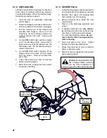
Страница 27: ...6 Check that everyone is clear of machine before restarting engine 7 Start the engine engage the drive system and resume working 4 7 9 SEVERE PLUG 1 Follow the stopping procedure and wait for all movi...

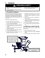
Страница 28: ...this procedure 1 Remove the tarpaulin if covered 2 Bring the collector bag to machine BXMC34B model 3 Review and follow the pre operation checklist OPERATING SAFETY Store the unit in an area away from...

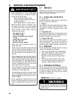
Страница 29: ...tion or oil changes IMPORTANT Do Not over grease Good maintenance is your responsibility Poor maintenance is an invitation to trouble Follow good shop practices Keep service area clean and dry Be sure...

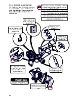
Страница 30: ...er blade check daily test sharpness every 50 hrs Shredder blades check daily test sharpness every 50 hrs Remove the belt shield to gain access to the grease zerk On a regular basis check all nuts bolt...

Страница 31: ...l L e v e l B e l t D r i v e P u l l e y A l i g n m e n t A i r C l e a n e r E n g i n e O i l C h i p p e r B l a d e s S h r e d d e r K n i v e s R o t o r B e a r i n g s E n g i n e O i l B e...

Страница 32: ...ith your fore finger and measure its defection Drive belt should deflect no more than 1 4 to 3 8 6 mm to 10 mm 4 If the belt requires adjustment loosen do not remove the 4 x bolts that hold the engine...

Страница 33: ...g unhook from the shield mount and brake clutch clutch keep unbolt from the shield mount 7 Remove the old belt from the rotor sheave first then the brake clutch 8 Replace with the new belt 9 Replace t...

Страница 34: ...s the stationary blade Be sure to tighten the blade mounting bolts to their specified torque when re installing the blades to the rotor 1 Ensure the engine is off ignition switch is off and the fuel v...

Страница 35: ...switch is off and the fuel valve is closed 2 Remove the 2 bolts that hold the upper rotor housing andcarefullyopentherotorhousing 3 Manually rotate chipper rotor plate so that one set of shredder kni...

Страница 36: ...e with guard removed Ledger Blades Each machine is equipped with a ledger stationary blade that acts as a shear for the moving rotor blades The ledger blade is designed with 4 usable corners When the...

Страница 37: ...creen in the bottom of the rotor frame The screen retains the wood material in the rotor chamber until it is small enough to exit through the holes and drop to the ground under the rotor The standard...

Страница 38: ...edure and replace belt Ensure machine is off Low engine speed Check that choke is off and throttle is set to maximum Blades and or knives are dull Rotate sharpen or replace blade and or knives Ensure...

Страница 39: ...ual for specific trouble shooting instructions requirements Obstructed discharge Clear debris from discharge chute BXMC34B or material screen BXMC34S Ensure machine is off Rotor plugged Inspect and cl...

Страница 40: ...arge W 1 5 38 MM Screen Machine Type Tires Dimensions W X L X H 40 x 43 x 49 38 x 43 x 47 Weight 270 LBS 250 LBS Screens Not Availalble 2 Options W 2 7 Cu Ft 28 Litres Mesh Bag 3 4 round screen 19MM 1...

Страница 41: ...19 33 53 80 115 160 290 420 630 17 36 63 100 155 220 305 540 880 1320 12 27 45 75 115 165 220 400 650 970 METRIC TORQUE SPECIFICATIONS 8 8 N m lb ft Bolt Torque Bolt Diameter A 10 9 N m lb ft M3 M4 M...

Страница 42: ...to go 1082A355 GARDEN TRACTOR HITCH 1012L269 1082A355 For models BXMC34S Conversion kit simple to install Makes a finer mulch than the standard screen 1074L240 3 4 ROUND SCREEN 19MM For models BXMC34S...

Страница 43: ...E 29 H HEARING LOSS 11 I INFORMATIVE LABELS 5 L LEDGER 30 LEDGER BLADES 36 M MAINTENANCE LABELS 5 MULCH COLLECTOR BAG 26 MULCHING SCREEN 37 N NOTICE 7 P PPE 8 11 15 22 23 25 PRODUCT LABELS 5 R ROTOR 2...

Отзывы: