background image

68

Maintenance Instructions 

ADJUSTMENTS

Step 2 - 

Blade Brake Band Adjustment

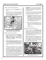
After the maximum pulley travel is set, adjust the 
working travel of the clutch idler pulley by adjusting 
the brake band nut and make the following adjust-
ment as needed:

1.  Adjust the blade brake band, using the adjust-

ment nut until pulley travel is approximately 
5/8 in. to 3/4 in. (16 mm to 19 mm) from en-
gaged to disengaged.

NOTE:

  As blade brake band/drum wears, pulley 

travel will increase and it will be necessary to 
adjust the blade brake band nut to maintain 
these dimensions.

CLUTCH DISENGAGED


CLUTCH ENGAGED


5/8 in. to 3/4 in. 

(16 mm to 19 mm)

Clutch Idler Pulley Travel Adjustment

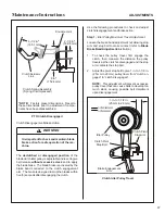
Blade Brake 

Band Adjustment Nut

Blade Brake 

Band

Chassis Mount 

(Ref)

Blade Brake Band Adjustment

2.  After adjustments are complete, check blade 

brake action as described in 

CHECKING/SER-

VICING

 the 

Blade Brake Action

 in this section.  

If blades do not stop within five (5) seconds, 
check the following:

a.  Make sure clutch and brake linkage are 

working freely (no binding).

b.  Check the brake band lining for wear.

c.  Check the brake drum on the pulley.  If exces-

sive wear is present, it will be necessary to 
replace worn parts.

Tilt-Up Deck Adjustable Stop

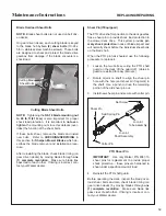
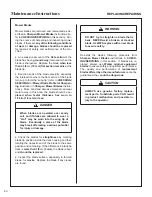
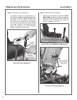
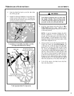
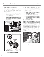
When the carrier frame hinge joint is properly ad-
justed, the deck lock levers should move in and out of 
the engaged and disengaged positions freely.  All 
four (4) hitch pins used for height adjustment should 
sit flush on the washers above the deck pin bushing.  
On a level surface, if any pin is sticking up (likely the 
front pins), tighten the opposite side or loosen the 
same side to lower the pin.  Adjustments are made by 
loosening the jam nut and tightening or loosen ing the 
set screws on the Deck Mount Pivot Brack 

ets. 


Retighten the jam nut when the adjustment is 
complete.

Set Screw

Jam Nut

Tilt-Up Deck Adjustable Stop

Содержание B18

Страница 1: ...Assembly Operating and Maintenance Instructions Please Read and Save These Instructions For Safety Read All Safety and Operation Instructions Prior to Operating Machine Beginning S N 125166 Effective...

Страница 2: ...y to the operator or others If any thing in this manual is confusing or hard to understand please contact your local authorized dealer or call our service department at 970 221 5614 for clarification...

Страница 3: ..._____________________ 21 PREOPERATING CHECKLIST______________ 22 Operating Instructions______________ 24 CONTROL IDENTIFICATION LOCATION AND FUNCTION ______________ 24 Ignition Switch_________________...

Страница 4: ...54 Ignition Wires_________________________ 54 Safety Switch System__________________ 54 Forward Speed Control Friction Lock______ 54 REPLACING REPAIRING__________________ 55 Drive Belts______________...

Страница 5: ...he tractor when the operator is seated facing forward in the tractor seat POWER TAKE OFF PTO transmits engine power to run the cutter blades RIGHT HAND RH refers to the right hand side of the tractor...

Страница 6: ...icing agent of the component manufacturer Any unauthorized work done on these components during the war ranty period may void the warranty If you have any difficulty finding an authorized outlet or ob...

Страница 7: ...d Cummins Fleetguard OptiAirTM Walker P N 2090 1 Primary 2090 3 Safety Filter ELECTRICAL SYSTEM Battery 12 Volt 300 CCA Charging System Flywheel Alternator Charging Output 16 Amp DC Regulated System P...

Страница 8: ...0 5 0 8 Infinitely Variable BLADE DRIVE PTO Shaft Sliding Spline Shaft with Two High Speed U Joints Blade Drive Clutch and Brake Manual Belt Tightener Clutch and Band Brake Stops Blades within Five 5...

Страница 9: ...ght lb kg Tractor Only 572 259 Tractor with 48 Mulch Deck DM48 2 803 364 DRIVE BELTS Engine PTO Walker P N 4230 1 Ground Drive Walker P N 4230 2 SEAT Contour Molded with Nylon Backed Vinyl Cover and I...

Страница 10: ...er Wheels Forward Speed Control FSC Friction Adjustment Tilt Up Latch Counterweight Springs and Protective Covers Deck Support Arm Tilt Up Deck Handle Deck Support Pins and Height Adjustment Hitch Pin...

Страница 11: ...fication 7 Rear View and Left Side View Left Hand Drive Wheel Footrest Cylinder Head Cooling Fins Fuel Tank and Cap Spread Axle Tail Wheel Tailwheel Fork and Wheel Muffler Tailpipe Fuel Pickup Line Oi...

Страница 12: ...e Fuel Tank Cap LH Transaxle LH Transaxle Lockout Arm Parking Brake Linkage Parking Brake Linkage RH Transmission Control Arm LH Transmission Control Arm Steering Lever Dampening Springs RH Transaxle...

Страница 13: ...ded by Walker Manufacturing must take full responsibility for safety The Walker Rider Lawnmower has been designed withmanysafetyfeaturestoprotecttheoperatorfrom personal harm or injury However it is n...

Страница 14: ...en gine should stop if the operator lifts off the seat with either the Forward Speed Control FSC out of the NEUTRAL PARK position or the PTO clutch in the ENGAGED position 10 Handle gasoline with car...

Страница 15: ...terlock switch normally prevents starting of the machine if these con trols are in the OPERATING position 7 Do not operate machine if the operator pres ence safety switch system is not working Verify...

Страница 16: ...orward with deck in tilt up position 18 In case of a clogged or plugged mower deck a Disengage the blade clutch PTO and turn the engine off before leaving the seat b LOOK to make sure blade drive shaf...

Страница 17: ...sely affects its operation perfor mance durability or use will VOID the war ranty and may cause hazardous conditions 8 Never attempt to disconnect any safety devices or defeat the purpose of these saf...

Страница 18: ...28 1 1 Warning thrown object hazard Keep bystanders away from the machine when operating Clear lawn of debris before operating Keep any discharge deflector in place and in the lowest position 2 Warni...

Страница 19: ...15 degrees 5 Warning thrown object hazard Keep bystanders away from the machine when operating 6 Choke 7 Warning entanglement hazard Keep all guards in place while engine is run ning 8 Parking brake...

Страница 20: ...cation Gearbox Cover Gear Drive Decks Only Part Number 8600 9 Location Rear Body Part Number 4107 12 1 Warning stop engine and remove ignition key before adjusting deck cutting height 1 Tighten blade...

Страница 21: ...ng a battery can be dangerous The battery should be taken to a reliable service station battery store or power equipment dealer where a trained techni cian can activate the battery safely DO NOT attem...

Страница 22: ...ill the battery Electrolyte will overflow through the vented caps onto parts of the machine and WILL result in se vere corrosion 3 Install battery Mower Deck Assembly Deck Caster Wheels Installation 1...

Страница 23: ...ector shield attached and in the lowest possible position Attach Shield Deck Discharge Shield Installation PTO Shaft Guard Installation Position the shaft guard as shown and mount with two 2 1 4 20 x...

Страница 24: ...ll the hitch pin through the hole on the end of each support arm to lock the deck in place re fer to Deck Counterweight Spring Installa tion photo Two 2 hitch pins are included in the Owner s Packet o...

Страница 25: ...m under the deck support pins on the low side to level the deck 3 Check the front to rear level Rotate the blades to point forward Measure the distance from bladetiptogroundonthefrontandrear Therear o...

Страница 26: ...cleaners deicers or moisture removing agents DO NOT use gasoline blended with methyl alcohol CHECK ENGINE CRANKCASE OIL LEVEL Check the engine crankcase oil level before use and after each 8 hours of...

Страница 27: ...lt Up Latch Tilt Up Hook Deck Lock Lever Tilt Up Hook and Latch Connected Deck Lift Handle Deck Secured in TILT UP Position CAUTION Do not operate machine with deck tilt up pivot joint unlocked DANGER...

Страница 28: ...after starting and S is the START position When start ing the engine turn the key clockwise to the S position Do not hold the key in the S position longer than 10 seconds If the engine does not start...

Страница 29: ...ck maintains the selected lever position Pulling back on the steering levers overrides the FSC setting and slows or stops for ward travel Releasing the steering levers allows the tractor to resume for...

Страница 30: ...e Engaged Parking Brake Disengaged Transaxle Lockout Arms The transaxle lockout arms disengage the transax les By lifting the arms up and locking them into place with the shoulder on the arm in the ch...

Страница 31: ...et function Procedure Interval Reminder Oil Change Break In 4 6 Hours C H G OIL Lubricate and Check Levels 24 26 Hours LUBE Oil Change 49 51 Hours C H G OIL These intervals reflect the actual time tha...

Страница 32: ...ng Levers RIGHT WHEEL STEERING LEVER Forward Position No Control Change Neutral Park Position LEFT WHEEL STEERING LEVER Reverse Drive Wheel Motion Position Fast Throttle Position Idle Position ON Posi...

Страница 33: ...wer DO NOT disconnect safety switches they are for the operator s protection 2 Move the choke lever to the ON position and move the throttle 1 4 to 1 2 open toward FAST Turn the ignition switch to the...

Страница 34: ...BEFORE operating on slopes Start maneuvering the mower with SLOW engine speed and SLOW Forward Speed Control setting until familiar with all operat ing characteristics Remember it is not necessary to...

Страница 35: ...teer by pulling the lever on the side of desired direction of turn e g pull the LH lever to turn left To minimize the possibility of overcontrol use only one hand on both steering levers Pull Steering...

Страница 36: ...the operator is not in the seat The function of this switch should be checked by the operator raising off the seat and engaging the blade clutch the en gine should stop If the switch is not work ing i...

Страница 37: ...king brake Also engaging the parking brake is recommended when stopping or parking the machine in a confined space with little tolerance for movement IMPORTANT The hydrostatic transaxles lock to preve...

Страница 38: ...move toward the center of the machine to engage the step that holds the arm in the UP unlocked position 3 The mower will freewheel with the arms in the LOCKOUT position The levers must be in the high...

Страница 39: ...the first pass and then make a second pass cutting to the desired height Use a slow setting on the FSC for trimming op erations Make sure the mower is leveled properly for a smooth cut Refer to Deck L...

Страница 40: ...tilt up position since both the roller wheels on the back of the deck may be damaged by moving the tractor The tilt up configuration should only be used when the tractor is parked The tractor body sho...

Страница 41: ...ve Tire Mounting Nuts 75 to 85 lb ft x 52 Check Blade Brake Action x x 53 Clean Transaxle Housing x 50 Check Air Filter Element x 48 Check Regap Spark Plugs x 53 Change Transaxle Oil and Filter x 45 R...

Страница 42: ...er System Use only Cummins Fleetguard air cleaner ele ments Aftermarket elements may not seal in the air cleaner housing allowing dirt to enter the engine Also aftermarket filters often skimp on the f...

Страница 43: ...e with the en gine stopped Also make sure the engine is cool and oil has had time to drain into the sump allow at least five 5 minutes after stopping the engine IMPORTANT NEVER check or add oil with t...

Страница 44: ...ter to keep dirt and debris out of the engine 5 Remove the old oil filter and wipe off the filter mounting surface on the engine 6 Apply a thin coating of new oil to the rubber gas ket on the replacem...

Страница 45: ...e lithium or molybdenum base grease for grease fittings and light machine oil SAE 10 to lubricate oil points Lubricate the locations shown in the Chassis and Deck Lubrication Points illustration NOTE...

Страница 46: ...rease 1 18 Transaxle Oil Reservoir Oil 20W 50 1 19 Tail Wheel Caster Fork Pivot Grease 2 20 RearAxle Pivot Grease 1 21 Rear Wheel Bearing Grease 2 22 Throttle Control Cable Ends Oil 2 23 Choke Control...

Страница 47: ...Maintenance Instructions LUBRICATION 43 Chassis and Deck Lubrication Points DS42 Shown 1 7 8 6 4 4 9 10 11 27 28 27 5 1 2 8 4 5 4 12 23 29 22 30 23 2 15 16 14 18 12 17 24 22 13 19 20 19 21 26 15 25...

Страница 48: ...he gearbox shaft parallel to cover plate NOTE In case the gearboxes are completely drained of oil approximately 5 fl oz 15 cl of oil per gearbox is required to refill the gear drive assembly NOTE Sinc...

Страница 49: ...50 API Service Class SL or higher oil through the opening where the elbows were Fill up to the opening 6 Before reinstalling the elbows screw the lock ing nut on the elbows down until they are snug th...

Страница 50: ...gshroudsremovedwillcause engine damage from overheating Clean these areas of dirt and debris Clean Cooling Fins and Fan Cylinder Head Cooling Fins It is essential for performance and longevity of the...

Страница 51: ...on the air cleaner outlet to indicate when the air filter needs servicing a yellow indicator will show when the filter is overly restricting airflow into the engine IMPORTANT Use only Cummins Fleetgua...

Страница 52: ...solution is not recommended Do not try to clean the element with compressed air Remember replacing a fil ter is less expensive than replacing a dusted engine 4 Use a bright light inside the element t...

Страница 53: ...r frame lift handle raise deck to the TILT UP position and insert the deck hook into the tilt up latch on the tractor body Tilt Up Latch Tilt Up Hook Deck Lock Lever Tilt Up Hook and Latch Connected D...

Страница 54: ...s This may be the result of an oil leak If an oil leak is noticed contact your local Walker dealer Cooling Fins Transaxle Housing and Cooling Fins IMPORTANT In case an oil leak develops on the input s...

Страница 55: ...Remove battery cell filler caps 2 Check the electrolyte level If the level is below the bottom of the vent well fill with distilled wa ter to the bottom of the vent wells 1 4 to 1 2 in 6 to 13 mm abo...

Страница 56: ...ightness 3 Check the blades for straightness by marking the blade tip position inside the deck housing and then rotating the opposite end of the blade to the same position and comparing If the dif fer...

Страница 57: ...eset the gap or replace with a new plug Clean spark plug with a wire brush If the electrodes are burned short or pitted replace the plug refer to Specifications for the proper type of replacement plug...

Страница 58: ...peed Control FSC or PTO is engaged Without an operator in the seat the engine con tinues to run with the Forward Speed Control FSC and or PTO engaged With an operator in the seat the Forward Speed Con...

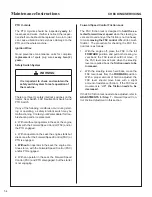
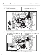
Страница 59: ...wires IMPORTANT ALWAYS use genuine factory re placement parts Substitute parts CAN result in product malfunction and possible injury to the op erator and or others Drive Belts There are three 3 indivi...

Страница 60: ...Open Engine Hidden for Clarity 2 To replace an engine PTO belt a Reverse the removal procedure to replace an engine PTO belt b Secure wire on lock pin above tab on lower PTO guard Engine PTO Belt Belt...

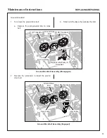
Страница 61: ...Slide belt off pulleys then release the idler Ground Drive Belt Assembly Disengaged 2 Reverse the procedure to install the ground drive belt Ground Drive Belt Assembly Engaged Depress Idler Pulley to...

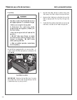
Страница 62: ...up spilled gasoline immediately and completely Model B18 is equipped with an in line fuel filter Vi sually inspect the filter periodically and replace the filter yearly In Line Fuel Filter Fuel Filter...

Страница 63: ...hear Pin If Equipped The PTO drive shaft connection to the deck gearbox has a shear pin to provide shock load protection to the mower deck drive This system provides pri mary shock protection in case...

Страница 64: ...e operated over sandy soil and if blades are allowed to wear a slot may be worn into the wing tip of blade Eventually a piece of the blade may break off creating a serious potential for injury or dama...

Страница 65: ...ection Step 1 Steering Lever Position Adjustment NOTE For proper operation the steering levers should be adjusted to sit evenly using the following procedure 1 Examine the steering levers to make sure...

Страница 66: ...le in position in the adjustment slide Adjust the han dles into the most comfortable position and tighten both locknuts Adjustment Slide Locknut Position Locknut Pivot Point Steering Handles Adjustmen...

Страница 67: ...SC in NEU TRAL PARK start the engine With the engine at normal operating speed check for movement of the drive wheels NOTE It may be necessary to tighten the FSC friction adjustment if the transmissio...

Страница 68: ...unterclockwise until neutral is restored Then lengthen the control rod on the slower side by turning the tracking adjustment nut counterclockwise until straight tracking and neutral are both achieved...

Страница 69: ...3 mm of the NEUTRAL PARK position If this distance is greater than 1 8 in 3 mm turn the adjustment bolt down slightly and recheck switch operation When finished adjusting tighten the jam nut and recon...

Страница 70: ...adjustment as follows Adjust the length of the clutch actuator link to achieve a clutch spring assembly bolt head clearance of 1 4 in to 5 16 in 6 35 mm to 7 94 mm with the clutch engaged To adjust l...

Страница 71: ...n five 5 seconds after disengaging the clutch Use the following procedures to check and adjust clutch disengagement and brake action Step 1 Idler Pulley Maximum Travel Adjustment Loosen the brake band...

Страница 72: ...tion as described in CHECKING SER VICING the Blade Brake Action in this section If blades do not stop within five 5 seconds check the following a Make sure clutch and brake linkage are working freely...

Страница 73: ...69 Operator s Notes...

Страница 74: ...70 Operator s Notes...

Страница 75: ...the product alterations or failure to follow the instructions contained in the Operator s Manual for operation and maintenance B The customer shall pay any charges for making service calls and or for...

Страница 76: ...WALKER MFG CO 5925 E HARMONY ROAD FORT COLLINS CO 80528 970 221 5614 FORM NO 011216 PRINTED IN USA www walkermowers com 2016 WALKER MFG CO...

Отзывы: