background image

9

Assembly Instructions 

The Walker Lawn Dethatcher will effectively dislodge 

excessive thatch from your lawn. Thatch is a layer of 

stems, clippings, runners, roots, and leaves that have 

not decayed. Excessive thatch prevents air, water, 

and fertilizer from reaching the roots.  These instruc-

tions will help ensure proper assembly and operation.

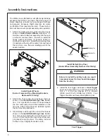
1.  Attach the caster wheel mounts to the tine tray as 

shown in 

Install Caster Wheels 

illustration.  In-

stall the caster fork/wheel assembly into the cast-

er wheel mount as shown.  Be sure to install the 

shock washer and three (3) spacers before in-

stalling the caster fork.  Install the remaining three 

(3) spacers at the top of the caster fork and install 

the lynch pin.  Use this as a starting point for the 

spacer location.

7

20

20

F255

F316

F316

F255

20

F434

F017

21

21

23 

580

9-2

25

F009


Install Caster Wheels  

(Carrier Frame and Tray Mounting Brackets 

Removed for Clarity)

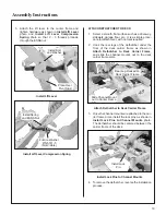
2.  Attach  the  tines  to  the  tine  tray  finger  tight,  as 

shown in the 

Install Dethatching Tines

 illustra-

tion.  It is important to be sure the loop between 

the tine coils nests around the hardware on the 

tine tray.  After all the tines are installed, tighten 

the tine mounting hardware.

3.  Insert safety rods through the coils of the tines as 

shown in the 

Install Dethatching Tines

 illustra-

tion.  Secure by bending the end of the rod 1-1/2 

in. to 2 in. from the end to prevent them from slip-

ping back through the tines.  The safety rod must 

be free to move slightly from side to side.

F571

Dethatching Tine

Tine Retainer Clip

F170

F009

Safety Rod

5809-2

Install Dethatching Tines 

(Caster Wheel Assembly Removed for Clarity)

  WARNING

Failure to install the safety rods can result 

in personal injury if a tine should disengage 

from the tine tray.

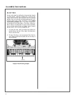
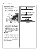
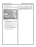
4.  Install the foot trigger as shown in 

Foot Trigger 

photo using the 5/16-18 x 1-3/4 Hex Bolt (F316), 

5/16 x 1 x 7/64 Flat Washer (F170), Washer 

(F060) and 5/16-18 ESNA Nut (F020).  Foot  

trigger should move freely after tightening nut.

Foot Trigger

Содержание A10

Страница 1: ...ompatible with decks 36 42 48 and 52 Please Read and Save These Instructions For Safety Read All Assembly and Operation Instructions Prior to Operating Attachment Beginning S N 2018 22223 P N 6605 15...

Страница 2: ...t be read and understood to help prevent possible injury to the operator or others If anything in this manual is confusing or hard to understand please contact your local authorized dealer or call our...

Страница 3: ...y Instructions 5 BEFORE OPERATING 5 OPERATING 6 MAINTENANCE 8 Assembly Instructions 9 ATTACH DETHATCHER TO DECK 10 ADJUST TINES 11 Operating Instructions 12 OPERATING THE DETHATCHER 12 TINE ACTION 12...

Страница 4: ...pindles and cutter blades FORWARD SPEED CONTROL FSC controls the maximum forward speed of the tractor func tioning as a cruise control LEFT HAND LH refers to the left hand side of the tractor when the...

Страница 5: ...difficulty finding an authorized outlet or obtain ing warranty service please contact our Service Department for assistance Walker Manufacturing Company 5925 E Harmony Road Fort Collins CO 80528 1 97...

Страница 6: ...cm 35 75 91 Width in cm 41 104 Length in cm 25 64 Overall Length Installed on Tractor in cm 107 75 274 Weight lb kg 55 25 NOTE The manufacturer reserves the right to make changes in specifications sh...

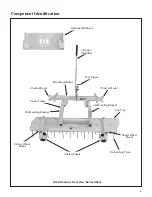
Страница 7: ...iew Not Installed Tine Tray Dethatching Tines Caster Wheels LH Mounting Bracket RH Mounting Bracket Mounting Bracket Foot Trigger Carrier Frame Channel Mount Channel Mount Lift Lever Foldable Caster W...

Страница 8: ...safety features to protect the operator from personal harm or injury However it is neces sary for the operator to use safe operating proce dures at all times Failure to follow safety instruc tions co...

Страница 9: ...rting the engine 12 Never attempt to make any adjustments while the engine is running except where specifically instructed to do so 13 The electrical system battery contains sulfuric acid Avoid any co...

Страница 10: ...bucking motion due to operator overcontrol If bucking does occur immediate ly stop the bucking action by pulling the For ward Speed Control FSC lever into the NEU TRAL PARK position 12 Disengage the P...

Страница 11: ...ust be running to perform a maintenance adjustment keep hands feet and clothing away from moving parts Do not wear jewelry or loose clothing 6 Always use proper engine service manuals when working on...

Страница 12: ...emoved for Clarity 2 Attach the tines to the tine tray finger tight as shown in the Install Dethatching Tines illustra tion It is important to be sure the loop between the tine coils nests around the...

Страница 13: ...s a simple proce dure for attachment with no tools required 2 Hook the rear legs of the dethatcher under the front of the deck carrier frame as shown in Attach Dethatcher to Deck Carrier Frame and sli...

Страница 14: ...ing Height photo The tines should touch the surface when pushed back If the tine vertical po sition needs to be adjusted use the spacer washers on the caster wheel forks as follows each spacer washer...

Страница 15: ...ch er there is resistance due to the tines being en gaged It is easier to disengage the tines by stopping the tractor forward motion and revers ing the tractor while lifting TINE ACTION Grass should b...

Страница 16: ...parts from which paint has worn NOTE Rustproofing or painting every year will prolong the life of the dethatcher 3 When the dethatcher is dry apply oil to tines to prevent rust Apply lubricant libera...

Страница 17: ...No No Location Type Places 1 Caster Wheel Mounts Grease 2 2 Carrier Frame Pivot Oil 2 3 Foot Trigger Pivot Oil 1 Grease every twenty five 25 hours A10 Lubrication Points Diagram 1 Caster Wheel Mount G...

Страница 18: ...Spacer Tube 2 16 6605 6 Tine Deflector 4 17 6610 Dethatching Tine 12 18 6608 2 Safety Rod 42 2 19 7775 6 Wire Lock Pin 2 1 2 2 20 8662 5 Square Plug 1 x 1 6 21 6770 2 Spacer 1 1 8 x 765 x 125 12 22 67...

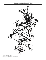
Страница 19: ...BLY A10 19 19 11 10 3 9 9 2 1 7 20 4 20 20 20 25 5 F316 12 F013 F013 F013 F013 F020 F551 F571 F571 F551 F316 F060 F009 F255 F316 F316 F009 F255 26 27 F170 F049 F009 25 20 F009 F009 20 6 F009 F020 18 F...

Страница 20: ...________________________ ______________________________________________________________________________________________________________ ________________________________________________________________...

Страница 21: ...________________________ ______________________________________________________________________________________________________________ ________________________________________________________________...

Страница 22: ...________________________ ______________________________________________________________________________________________________________ ________________________________________________________________...

Страница 23: ...k is performed Warranty service can be arranged by contacting the dealer where you purchased the attachment or by contacting Walker Manufacturing Company 5925 East Harmony Road Ft Collins CO 80528 Pro...

Страница 24: ...WALKERMFG CO 5925E HARMONYROAD FORTCOLLINS CO80528 970 221 5614 FORM NO 012618 PRINTED IN USA www walker com 2017 WALKER MFG CO...

Отзывы: