Waldorf RN8400E Скачать руководство пользователя страница 15

13 

Electrical Connection 

NOTE: ALL ELECTRICAL CONNECTIONS MUST ONLY BE CARRIED OUT BY A QUALIFIED 

SERVICE PERSON. 


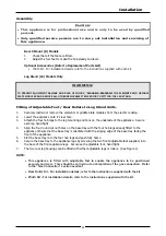
Each appliance should be connected to an adequately protected power supply and isolation switch mounted 

adjacent to, but not behind the appliance.  This switch must be clearly marked and readily accessible in 

case of fire. 


1. 

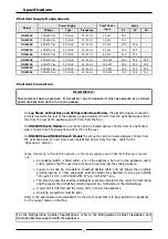
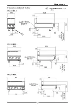
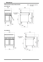
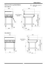
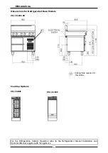
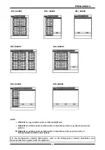
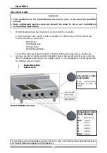
Check that the electricity supply is correct as shown on the Rating Plate.  Refer to the 'Dimensions 
Section’ for rating plate locations for the different model types. 
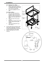
2. 

The supply terminal connections are located at the rear of the the Cooktop.  Refer to ‘Electrical 

Connections’ in the ‘Specifications’ section of the manual. 

3. 

Bring the supply cable up through the compression type gland provided on the rear of the main 

electrical switchgear panel.


4. 

Connect the mains supply to L1, L2 and L3 connections as required.  Refer to the 'Electrical Supply 
Requirements' section.


5. 

Connect neutral and earth conductors to neutral stud and earth stud respectively. 

6. 

For all connections ensure that conductors are secure and appropriately terminated. 

7. 

Tighten the cable gland to secure against tension on the cable. 


NOTE: 

• 

This appliance must be earthed. 

• 

Fixed wiring installations must incorporate an all-pole disconnection switch. 


8. 

Correctly locate the appliance into its final operating position and using a spirit level, adjust the legs 

so that the appliance is level and at the correct height. 

9. 

Connect the power supply to the appliance. 

10.  Check that the electrical supply is as shown in “Specifications” section. 


Commissioning 

1. 

Before leaving the new installation; 

a.  Check the following functions in accordance with the operating instructions specified in the 

‘Operation’ section of this manual. 

• 

Check the current draw and loading for the equipment.  Refer specification section for 
correct electrical requirements. 

• 

C

heck that all the connections are correct and that all cover panels have been re-fitted. 

• 

Check that the appliance functions in accordance with the operating instructions.


• 

Ensure that this instruction manual is left with the appliance. 

• 

Ensure that all the relevant details and contacts have been added to the front of this 
manual. 


b.  Ensure that the operator has been instructed in the areas of correct operation and shutdown 

procedure for the appliance. 


2. 

This manual must be kept by the owner for future reference and as a record of 

Date of Purchase,


Date of Installation 

and 

Serial Number of Unit 

recorded and kept with this manual.  

(These 

details can be found on the Rating Plate attached to the inner R/H side panel.  Refer to 

the ‘Dimensions’ section for rating plate location)


NOTE: 

• 

If for some reason it is not possible to get the unit to operate correctly, turn off the  
electrical power supply and contact a qualified service person.  The supplier of this unit 
will be able to recommend a suitable person. 

• 

Make sure that the electrical supply is turned off before any service or maintenance work is 
carried out.


Installation


WARNING: 


T

HIS


APPLIANCE


MUST


BE


EARTHED

.  I

F


THE


SUPPLY


CORD


IS


DAMAGED

IT


MUST


BE


REPLACED


BY


A


SUITABLY


QUALIFIED


PERSON


IN


ORDER


TO


AVOID


A


HAZARD

Содержание RN8400E

Страница 1: ...t a l l a t i o n a n d O p e r a t i o n M a n u a l Electric Cooktop Series RN8200E RN8400E RN8600E Date Purchased Serial Number Dealer Service Provider 230558 7 For use in GB IE RNL8200E RNL8400E R...

Страница 2: ...0257 Fax 336 661 9546 CANADA Serve Canada 22 Ashwarren Road Downview Ontario M3J1Z5 Toll Free 800 263 1455 Ph 416 631 0601 Fax 416 631 0315 info servecanada com www servecanada com www moffat com NEW...

Страница 3: ...nstallation 10 Installation Requirements Unpacking Location Clearances Assembly Fitting Adjustable Feet Rear Rollers to Leg Stand Units Fitting Adjustable Feet Rear Rollers to Cabinet and Refrigeratio...

Страница 4: ...T ALTERATION SERVICE OR MAINTENANCE CAN CAUSE PROPERTY DAMAGE INJURY OR DEATH READ THE INSTALLATION OPERATING AND MAINTENANCE INSTRUCTIONS THOROUGHLY BEFORE INSTALLING OR SERVICING THIS APPLIANCE WARN...

Страница 5: ...Cabinet Base excluding RN8200G series LS Leg Stand excluding RN8200G series RB Refrigerated Base RN8600G and RN8800G series only General A commercial heavy duty high efficiency Cooktop for modular ki...

Страница 6: ...IEC 60245 IEC 57 e g HO5 RN F Type The branch supply line shall be individually overload protected to the correct current rating and the supply chord shall be protected against any mechanical or ther...

Страница 7: ...5 Dimensions Dimensions for Bench Models RN L 8200E B RN L 8600E B Rating Plate Location for this option R RN L 8400E B R...

Страница 8: ...6 Dimensions Dimensions for Cabinet Base Models RN L 8400E CB RN L 8600E CB Rating Plate Location for this option R R...

Страница 9: ...7 Dimensions Dimensions for Leg Stand Models RN L 8400E LS RN L 8400E LS Rating Plate Location for this option R R...

Страница 10: ...ase Models RN L 8600E RB RN L 8200E Cooktop Options For the Refrigeration Cabinet Operation refer to the Refrigeration Cabinet Installation and Operation Manual supplied with the appliance Rating Plat...

Страница 11: ...S model options RN8600E is available as Bench Mount B Cabinet Base CB Leg Stand LS or Refrigerated Base RB model options For the Refrigeration Cabinet Dimensions refer to the Refrigeration Cabinet Ins...

Страница 12: ...t to the relevant codes and manufacturer s specifications shown in this section will void the warranty Unpacking Remove all packaging and transit protection from the appliance including all protective...

Страница 13: ...egs and push fully home 6 Secure the base tray to the appliance legs by screwing the two front adjustable feet supplied into the base of the front appliance legs Secure each adjustable foot hand tight...

Страница 14: ...nd tighten up the bolts using a 24mm socket b Fit the rear rollers to the rear leg supports c Secure the rear rollers to the rear leg supports using the locating bolts supplied d Tighten the locating...

Страница 15: ...pliance 10 Check that the electrical supply is as shown in Specifications section Commissioning 1 Before leaving the new installation a Check the following functions in accordance with the operating i...

Страница 16: ...To use this appliance correctly please read the following sections carefully Radiant Hotplates Griddle Plate Model RN8603E B Shown Operation For the Refrigeration Cabinet Description of Controls refer...

Страница 17: ...at bases Any part of the hotplate which glows bright red is not making effective contact with the base of the utensil and this decreases the life and efficiency of the hotplate Utensils which are sign...

Страница 18: ...op clean and operating at peak efficiency follow the procedures shown below After Each Use 1 Clean the griddle with a scraper tool to remove any food debris 2 Always ensure that the scraper tool blade...

Страница 19: ...ooktop that the module is located d Remove the drip tray from beneath the element and wash with hot water and a detergent solution Dry with a soft dry cloth e Clean beneath the element using a cloth m...

Страница 20: ...spread over the griddle in order to form a protective film Cooktop Cooking Area a Clean the Cooktop area with a soft cloth and a mild detergent and hot water solution b Baked on deposits or discoloura...

Страница 21: ...of the Appliance both can be found on the Technical Data Plate located on the appliance Fault Possible Cause Remedy Element does not work when turned ON Check individual fuses located behind the cont...

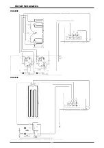
Страница 22: ...20 Circuit Schematics RN8200E RN8203E...

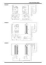
Страница 23: ...21 Circuit Schematics RN8400E RN8403E RN8406E...

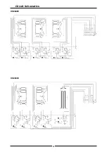
Страница 24: ...22 Circuit Schematics RN8600E RN8603E...

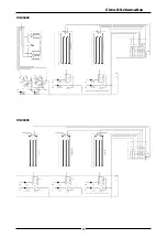
Страница 25: ...23 Circuit Schematics RN8606E RN8609E...

Страница 26: ...7851 Adjustable Legs 150mm Leg Base Stand Ext d Thread 232351 Rear Roller Assy 3 228288 Grease Tray Griddle 228881 Spill Tray 300mm 228882 Spill Tray 600mm 228883 Spill Tray 450mm 229069 Element Frame...

Страница 27: ......

Отзывы: