background image

43

Dati tecnici

ITA

12.  Dati tecnici

NOTA:

 valgono le informazioni riportate 

sulla targhetta dell’apparecchio d’illumina-

zione che si trova sul cavo di collegamento 

dell’apparecchio d’illuminazione.

12.1  Dimensioni

Descrizione

Valore

Testa dell'appa-

recchio d'illumi-

nazione

Diametro: 

82 mm
Altezza: 

99 mm

Braccio flessi-

bile  

Testa snodata

SL

F

 500/750/(S): 

750 mm 
SL

J

 500/750/S: 

185 mm

Tab. 4: Dimensioni.

12.2  Valori elettrici

Denomina-
zione

Valore

Gamma di 

tensione

La gamma di tensione 

è indicata sulla tar-

ghetta dell’apparecchio 

d’illuminazione.

Gamma di fre-

quenza

La gamma di fre-

quenza è indicata sulla 

targhetta dell’apparec-

chio d’illuminazione.

Potenza assor-

bita

La potenza assorbita è 

indicata sulla targhetta 

dell’apparecchio d’illu-

minazione.

Alimentatore

Integrato

Tab. 5: Valori elettrici.

12.3  Classificazioni

Denominazione Valore

Classe di isola-

mento

- Apparecchio  

  d’illuminazione


III

Denominazione Valore

- Apparecchio  

d’illumin 

apparecchio di 

comando


II

Grado di 

protezione

IP 67

Modo operativo

Funzionamento 

 continuo

Valutazione 

fotobiologica a 

norma EN 62471

Gruppo di rischio 1

Temperatura 

ambiente max. 

consentita

40°C 

Tab. 6: Classificazioni.

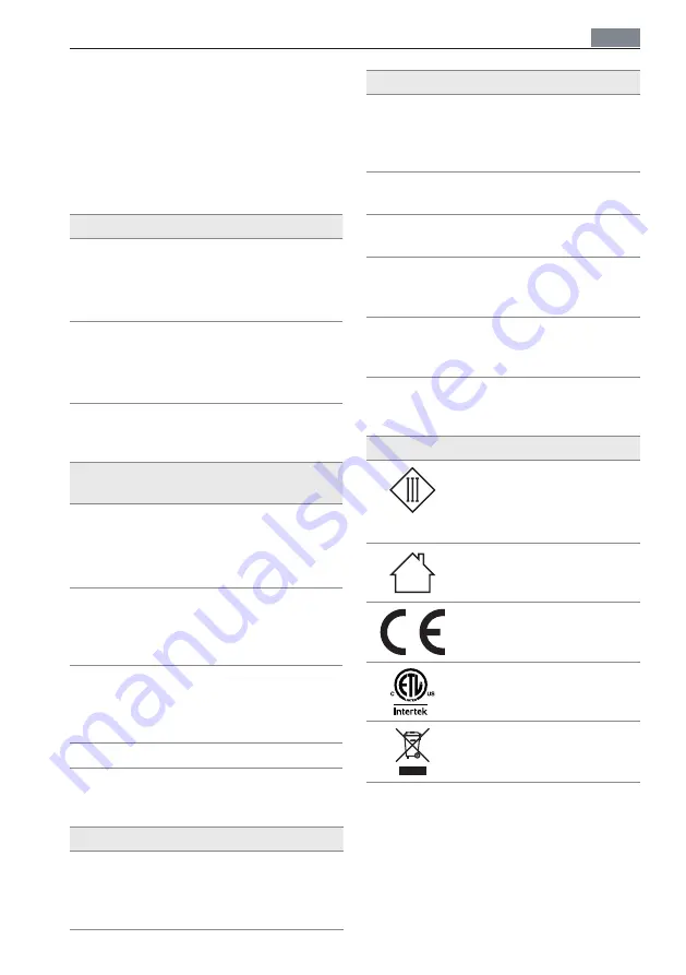
12.4  Simboli

Simbolo

Denominazione

Classe di protezione 

III

Funzionamento con bas-

sissima tensione di sicu-

rezza (SELV)
Solo per uso interno.

Marcatura di conformità 

CE

Omologazione ETL

Smaltimento secondo la 

direttiva europea WEEE 

(RAEE).

Tab. 7: Simboli.

Содержание SLF 500

Страница 1: ...Gebrauchsanweisung DEU Instructions For Use ENG Mode d emploi FRA Istruzioni per l uso ITA Maschinenleuchte Machine Light Luminaire pour machine Apparecchio d illuminazione per macchine SLJ SLF ...

Страница 2: ......

Страница 3: ...3 DEU ENG ITA FRA Inhaltsverzeichnis 4 Table of Contents 14 Sommaire 24 Indice 34 ...

Страница 4: ...stigungs element montieren 8 4 Positionieren 9 5 Anschließen 9 5 1 Leuchte an Netzspannung anschließen Netzversion 9 5 2 Leuchte an 24 V Versorgungsspannung anschließen SELV Version 10 6 Bedienen 10 6 1 Ein und Ausschalten 10 7 Was tun wenn 11 8 Leuchtmittel wechseln 12 9 Reinigen 12 10 Reparieren 12 11 Entsorgen 12 12 Technische Daten 13 12 1 Abmessungen 13 12 2 Elektrische Werte 13 12 3 Klassifi...

Страница 5: ... auf dem Leis tungsschild angegeben sind und sicher stellen dass sie identisch sind X X Beschädigte Anschlussleitung sofort von der Stromversorgung trennen und vom Hersteller von einem vom Herstel ler beauftragten Servicetechniker oder von einer vergleichbar qualifizierten Per son ersetzen lassen X X Wartungs und Reparaturarbeiten nur vom Hersteller oder von einem vom Hersteller beauftragten Servi...

Страница 6: ...rahlung vermeiden 1 3 Warnstufen im Dokument GEFAHR Warnung vor Gefahren die bei Missachtung der Maßnahmen unmittelbar zuTod oder schweren Verletzungen führen WARNUNG Warnung vor Gefahren die bei Missachtung der Maßnahmen zu Tod oder schweren Verletzungen führen können VORSICHT Warnung vor Gefahren die bei Missach tung der Maßnahmen zu Verletzungen führen können ACHTUNG Warnung vor Gefahren die be...

Страница 7: ...er die Leuchte hat X X Bestimmen Sie anhand der folgenden Tabelle das Leuchtenmodell siehe Tab 1 Beispiel Die Modellnummer SLF 500 750 S steht für folgendes Leuchtenmodell SL F 500 750 S Maschinen leuchte Gestängeart F Flexschlauch Lichtstrom ca 500 lm Farbcode Ra 70 5000 K SELV Version Typ Gestängeart Lichtstrom Farbcode Anschluss SL Maschinen leuchte F Flexschlauch J Gelenkkopf ca 500 lm 750 Far...

Страница 8: ... HINWEIS Beachten Sie das Bohrbild siehe Fig 2 X X Schrauben Sie das Befestigungsele ment mit vier geeigneten Schrauben an die Montageoberfläche siehe Fig 1 3 2 Leuchte an Befestigungs element montieren B A Fig 3 Leuchte an Befestigungselement montieren X X Drehen Sie die Schraube B aus dem Befestigungselement heraus siehe Fig 3 X X Stecken Sie den Zapfen A der Leuchte in die Öffnung des Befestigu...

Страница 9: ...verharrt siehe Fig 4 5 Anschließen 5 1 Leuchte an Netzspannung anschließen Netzversion VORSICHT Stromschlag durch eindringende Feuchtigkeit Personenschaden und Beschädigung des Steckernetzteils X X Steckernetzteil außerhalb feuchter Umgebung einstecken ACHTUNG Sachschaden durch falscheAnschluss spannung Zerstörung oder Beschädigung der Leuchte X X Netzspannung mit Nennspannung und Frequenz verglei...

Страница 10: ...erheitskleinspannung SELV betreiben X X USA und Kanada Dieses Gerät muss mit einem Netzteil der Klasse 2 verbunden werden Farbe Belegung braun DC blau DC Tab 2 Belegung der Adern HINWEIS Die Leuchte ist gegenVerpolung geschützt X X Verbinden Sie die beiden Adern mit einer geeigneten Stromversorgung 6 Bedienen 6 1 Ein und Ausschalten Leuchte mitTaste ein und ausschalten A Fig 6 Taste X X Um die Leu...

Страница 11: ...lussleitung ist beschädigt Mechanische Ein wirkung auf die Anschlussleitung X X Beschädigte Anschlussleitung sofort von der Stromversorgung trennen und vom Hersteller von einem vom Hersteller beauftrag ten Servicetechniker oder von einer vergleichbar qualifizierten Person ersetzen lassen Falls Sie unseren Service in Anspruch nehmen möchten sind unsere Experten für Sie erreichbar Service Hotline 49...

Страница 12: ...fläche prüfen X X Reinigen Sie die Leuchte mit einemTuch und einem milden Reiniger 10 Reparieren ACHTUNG Sachschaden durch unsachgemäße Reparatur Zerstörung oder Beschädigung der Leuchte X X Reparaturen nur vom Hersteller oder von Fachpersonal durchführen lassen das vom Hersteller geschult ist X X Nur vom Hersteller freigegebene Ersatzteile verwenden 11 Entsorgen Die Leuchte unterliegt der europäi...

Страница 13: ... auf dem Leistungsschild der Leuchte angegeben Leistungs aufnahme Die Leistungsauf nahme ist auf dem Leistungsschild der Leuchte angegeben Betriebsgerät integriert Tab 5 Elektrische Werte 12 3 Klassifizierungen Bezeichnung Wert Schutzklasse Leuchte Leuchte Betriebsgerät III II Bezeichnung Wert Schutzart IP 67 Betriebsart Dauerbetrieb Photobiologische Bewertung nach EN 62471 Risikogruppe 1 Maximal ...

Страница 14: ...o the fastening element 18 4 Positioning 19 5 Connection 19 5 1 Connecting the luminaire to the mains voltage mains version 19 5 2 Connecting the luminaire to the 24V supply voltage SELV version 20 6 Operation 20 6 1 Switch on and switch off 20 7 What to do if 21 8 Replacing the lamp 22 9 Cleaning 22 10 Repair 22 11 Disposal 22 12 Technical Data 23 12 1 Dimensions 23 12 2 Electrical values 23 12 3...

Страница 15: ...r use and faulty work on the lumi naire may result in injuries and material damage X X Compare the mains voltage with the nominal voltage and the frequency specified on the rating plate and make sure that they are identical X X Disconnect a damaged connecting cable immediately from the power sup ply and have it replaced by the manufac turer by a service technician authorised by the manufacturer or...

Страница 16: ...e of the elec tronic components X X Do not exceed the maximum permissi ble ambient temperature X X Avoid direct exposure to sunlight 1 3 Warning levels in the document DANGER Warning against hazards that result directly in serious injuries or death in case of non observance WARNING Warning against hazards that may result in serious injuries or death in case of non observance CAUTION Warning agains...

Страница 17: ...e has X X Determine the luminaire model by referring to the following table see Tab 1 Example The model number SLF 500 750 S stands for the following luminaire model SL F 500 750 S Machine light Arm type F Flexible tube Light current approx 500 lm Colour code Ra 70 5000 K SELV version Type Arm type Light current Colour code Connection SL Machine light F Flexible tube J Pivoting head approx 500 lm ...

Страница 18: ...nt Fig 2 Hole pattern NOTE Observe the hole pattern see Fig 2 X X Screw the fastening element to the mounting surface using four suitable screws see Fig 1 3 2 Mounting the luminaire to the fastening element B A Fig 3 Mounting the luminaire to the fasten ing element X X Unscrew the screw B from the fasten ing element see Fig 3 X X Insert the stud A of the luminaire into the opening of the fastening...

Страница 19: ...5 Connection 5 1 Connecting the luminaire to the mains voltage mains ver sion CAUTION Electric shock caused by ingress of moisture Personal injury and damage to the plug in power supply unit X X Plug in plug in power supply unit away from a moist environment NOTICE Material damage caused by wrong mains voltage Damage or destruction of the luminaire X X Compare the mains voltage with the nominal vo...

Страница 20: ...tra low voltage SELV only X X USA and Canada This device must be connected to a class 2 power supply Farbe Assignment brown DC blue DC Tab 2 Assignment of the wires NOTE The light is protected against polar ity reversal X X Connect both wires to a suitable power supply 6 Operation 6 1 Switch on and switch off Switching the luminaire on and off by pressing the key A Fig 6 Key X X To switch the lumi...

Страница 21: ... connecting cable is damaged Mechanical impact on the connecting cable X X Disconnect a damaged connect ing cable immediately from the power supply and have it replaced by the manufacturer by a service technician authorised by the man ufacturer or by a person with com parable qualification If you want to make use of our service our experts can be reached at Service Hotline 49 0 77 20 6 01 170 Serv...

Страница 22: ...e with the surface X X Clean the luminaire with a cloth and a mild detergent 10 Repair NOTICE Material damage caused by improper repair Damage or destruction of the luminaire X X Have repairs performed only by the manufacturer or skilled personnel trained by the manufacturer X X Use only spare parts approved by the manufacturer 11 Disposal The luminaire is subject to the European WEEE Directive X ...

Страница 23: ...d on the rating plate of the luminaire Power con sumption The power consump tion is specified on the rating plate of the luminaire Operating unit integrated Tab 5 Electrical values 12 3 Classifications Designation Value Protection class Light Light operating unit III II Degree of protection IP 67 Operating mode Continuous operation Photobiological assessment accord ing to EN 62471 Risk group 1 Max...

Страница 24: ...4 Positionner le luminaire 29 5 Raccorder le luminaire 29 5 1 Raccorder le luminaire à la tension de réseau variante réseau 29 5 2 Raccorder le luminaire à la tension d alimentation 24 V variante SELV 30 6 Utiliser le luminaire 30 6 1 Allumer et éteindre le luminaire 30 7 Que faire si 31 8 Remplacer les lampes 32 9 Nettoyage 32 10 Réparer le luminaire 32 11 Élimination 32 12 Données techniques 33 ...

Страница 25: ...i ci peuvent entraî ner des blessures et des dommages maté riels X X Comparer la tension du secteur avec la tension nominale et la fréquence indi quées sur la plaque signalétique et s as surer qu elles sont identiques X X Séparer un câble de raccordement endommagé immédiatement de l ali mentation en courant et le faire rem placer exclusivement par le fabricant un technicien du service après vente ...

Страница 26: ...pérature ambiante maximale admissible ne doit pas être dépassée X X Éviter un rayonnement solaire direct 1 3 Niveaux d avertissement dans le document DANGER Avertissement relatif à des dangers entraî nant immédiatement la mort ou des bles sures graves en cas de non application des mesures indiquées AVERTISSEMENT Avertissement relatif à des dangers pouvant entraîner la mort ou des blessures graves ...

Страница 27: ...naire X X Déterminez le modèle de luminaire à l aide du tableau suivant voir Tab 1 Exemple Le numéro de modèle SLF 500 750 S correspond au modèle de luminaire suivant SL F 500 750 S Luminaire pour machine Type de tige F Bras flexible Flux lumineux env 500 lm Code couleur Ra 70 5000 K Variante SELV Type Type de tige Flux lumineux Code couleur Raccordement SL Luminaire pour machine F Bras flexible J...

Страница 28: ... de perçage REMARQUE Respecter le schéma de per çage voir Fig 2 X X Visser l élément de fixation sur la sur face de montage à l aide de quatre vis appropriées voir Fig 1 3 2 Monter le luminaire sur l élé ment de fixation B A Fig 3 Monter le luminaire sur l élément de fixation X X Dévisser la vis B hors de l élément de fixation voir Fig 3 X X Introduire le tourillon A situé sur le lumi naire dans l...

Страница 29: ...order le luminaire 5 1 Raccorder le luminaire à la ten sion de réseau variante réseau ATTENTION Risque d électrocution en cas de pénétration d humidité Dommages corporels et endommage ment du bloc d alimentation sur fiche X X Ne pas insérer le bloc d alimenta tion sur fiche dans un environne ment humide AVIS Dommages matériels dus à une ten sion d alimentation erronée Détérioration ou destruction ...

Страница 30: ... une très basse tension de sécurité SELV X X USA et le Canada Cet appareil doit être raccordé à un bloc d ali mentation de la classe 2 Couleur Assignation marron DC bleu DC Tab 2 Assignation des conducteurs REMARQUE Le luminaire est protégé contre l inversion de polarité X X Raccorder les deux brins à une alimen tation appropriée 6 Utiliser le luminaire 6 1 Allumer et éteindre le lumi naire Allume...

Страница 31: ...est endom magé Effet mécanique sur le câble de raccorde ment X X Séparer un câble de raccordement endommagé immédiatement de l alimentation en courant et le faire remplacer exclusivement par le fabricant un technicien du service après vente mandaté par celui ci ou une personne disposant d une qualification comparable En cas de besoin contactez les experts de notre service après vente Ligne directe...

Страница 32: ...ettoyez la lampe avec un tissu et un nettoyant doux 10 Réparer le luminaire AVIS Dommages matériels dus à une répa ration non conforme Détérioration ou destruction du luminaire X X Les réparations ne doivent être effec tuées que par le fabricant ou par un personnel qualifié formé par le fabri cant X X Seul l emploi de pièces de rechange agréées par le fabricant est auto risé 11 Élimination Le lumi...

Страница 33: ...ique du luminaire Puissance absorbée La puissance absor bée est indiquée sur la plaque signalétique du luminaire Appareil de commande intégré Tab 5 Valeurs électriques 12 3 Classifications Désignation Valeur Classe de protection Luminaire Luminaire appareillage III II Désignation Valeur Indice de protection IP 67 Mode de fonction nement Fonctionnement continu Évaluation photo biologique selon la n...

Страница 34: ...ento di fissaggio 38 4 Posizionamento 39 5 Collegamento 39 5 1 Collegamento dell apparecchio d illuminazione alla tensione di rete versione di rete 39 5 2 Collegamento dell apparecchio d illuminazione alla tensione di alimentazione 24 V versione SELV 40 6 Comando 40 6 1 Accensione e spegnimento 40 7 Cosa fare se 41 8 Sostituzione della lampada 42 9 Pulizia 42 10 Riparazione 42 11 Smaltimento 42 12...

Страница 35: ...a L uso inappropriato e scorretto dell apparec chio può provocare lesioni e danni materiali X X Assicurarsi che la tensione di rete corri sponda alla tensione nominale e alla fre quenza indicate sulla targhetta X X Disinserire immediatamente l alimen tazione elettrica del cavo di collega mento danneggiato e farlo sostituire dal costruttore da un tecnico di assistenza incaricato dal costruttore o d...

Страница 36: ...enti elettronici X X Non superare la temperatura ambiente massima consentita X X Evitare l irradiazione solare diretta 1 3 Livelli di pericolo nel documento PERICOLO Pericoli che in caso di mancata osservanza delle misure causano immediatamente gravi lesioni oppure anche la morte AVVERTENZA Pericoli che in caso di mancata osser vanza delle misure possono causare gravi lesioni oppure anche la morte...

Страница 37: ...minare in base alla tabella seguente il modello dell apparecchio vedi Tab 1 Esempio il numero di modello SLF 500 750 S sta per il modello d apparecchio d illu minazione seguente SL F 500 750 S Apparec chio d illumi nazione per macchine Tipo di asta F Braccio fles sibile Flusso lumi noso ca 500 lm Codice cromatico Ra 70 5000 K Versione SELV Tipo Tipo di asta Flusso lumi noso Codice croma tico Colle...

Страница 38: ...rispettare lo schema di foratura vedi Fig 2 X X Avvitare l elemento di fissaggio mediante quattro viti appropriate alla superficie di montaggio vedi Fig 1 3 2 Montaggio dell apparecchio d illuminazione sull elemento di fissaggio B A Fig 3 Montare l apparecchio d illuminazione sull elemento di fissaggio X X Rimuovere la vite B dall elemento di fis saggio vedi Fig 3 X X Inserire il perno A dell appa...

Страница 39: ...la posi zione desiderata vedi Fig 4 5 Collegamento 5 1 Collegamento dell apparec chio d illuminazione alla ten sione di rete versione di rete ATTENZIONE Folgorazione dovuta alla penetra zione di umidità Danni alle persone e danneggiamento dell alimentatore a spina X X Inserire l alimentatore a spina al di fuori di un ambiente umido AVVISO Danni materiali dovuti a tensione di collegamento errata Da...

Страница 40: ...nsione di sicurezza SELV X X USA e Canada Questo apparec chio deve essere collegato ad un a limentatore della classe 2 Colore Assegnazione marrone DC blu DC Tab 2 Assegnazione dei conduttori NOTA L apparecchio è protetta contro l in versione dei poli X X Collegare i due fili a un alimentazione elettrica idonea 6 Comando 6 1 Accensione e spegnimento Accensione e spegnimento dell apparec chio con ta...

Страница 41: ...i collega mento è danneggiato Effetto meccanico sul cavo di collegamento X X Disinserire immediatamente l a limentazione elettrica del cavo di collegamento danneggiato e farlo sostituire dal costruttore da un tecnico di assistenza incaricato dal costruttore o da persona qua lificata in maniera analoga Nel caso in cui si desideri prendere contatto con il nostro servizio di assistenza i nostri esper...

Страница 42: ...ire l apparecchio d illuminazione con un panno e un detergente non aggres sivo 10 Riparazione AVVISO Danni materiali dovuti a lavori di ripa razione eseguiti scorrettamente Danneggiamento o distruzione dell appa recchio d illuminazione X X Far eseguire le riparazioni solo dal costruttore o da personale tecnico specializzato addestrato dal costrut tore X X Utilizzare esclusivamente le parti di rica...

Страница 43: ...targhetta dell apparec chio d illuminazione Potenza assor bita La potenza assorbita è indicata sulla targhetta dell apparecchio d illu minazione Alimentatore Integrato Tab 5 Valori elettrici 12 3 Classificazioni Denominazione Valore Classe di isola mento Apparecchio d illuminazione III Denominazione Valore Apparecchio d illuminazione apparecchio di comando II Grado di protezione IP 67 Modo operati...

Страница 44: ...Nr 405 434 810 nB 06 2017 TB Printed in China Änderungen vorbehalten 28 06 2017 Herbert Waldmann GmbH Co KG Peter Henlein Straße 5 D 78056 Villingen Schwenningen Telefon 49 0 77 20 601 0 Telefax 49 0 77 20 601 290 www waldmann com info waldmann com ...

Отзывы: