42 System Description
WAGO-I/O-SYSTEM 750 XTR
750-352/040-000 FC ETHERNET G3 XTR
Manual
Version 1.3.0
3.7.2
Grounding Function
The grounding function increases the resistance against electro-magnetic
interferences. Some components in the I/O system have a carrier rail contact that
dissipates electro-magnetic interferences to the carrier rail.
Figure 20: Carrier Rail Contact (Example)
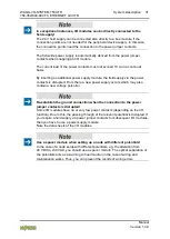
Ensure sufficient grounding is provided!
You must take care to ensure the direct electrical connection between the carrier
rail contact and the carrier rail.
The carrier rail must be grounded.
For information on carrier rail properties, see section “Mounting” > … > “Carrier
Rail Properties”.
The bottom CAGE
CLAMP
®
connectors of the supply modules enable optional
connection of a field-side functional ground. This potential is made available to
the I/O module arranged on the right through the spring-loaded contact of the
three power contacts. Some I/O modules are equipped with a knife-edge contact
that taps this potential. This forms a potential group with regard to functional
ground with the I/O module arranged on the left.
Pos: 19.16.46 /D okumentation allgemein/Gliederungselemente/---Sei tenwechsel--- @ 3\mod_1221108045078_0.docx @ 21810 @ @ 1


