32 Connect Devices
WAGO ETHERNET Accessories 852
852-1102 Industrial Switch
Manual
Version 1.2.0
6
Connect Devices
6.1
Power Supply
The industrial switch uses direct-current power supply for 9 … 57 V.
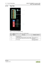
The primary and secondary network link is established via a 6-pin plug-in
connection located on the top of the industrial switch.
The female connector (order-no. 2231-106/026-000) is composed of six
connecting terminals and can be inserted and removed easily by hand to connect
to the 6-pin plug connector located on the top of the switch.
1.
Connect a suitable grounding conductor to the grounding lug on the top of
the switch.
Ground for the switch
The ground for the switch prevents electromagnetic interference from
electromagnetic radiation.
Observe the corresponding standards for EMC-compatible installations as well.
2.
Plug the female connector into the male connector of the switch if it has not
already been plugged in. Check the tight fit of the multipoint connector by
gently shaking it.
3.
PWR +/-:
To connect or disconnect the conductors, actuate the spring directly in the
female connector using a screwdriver or an operating tool and insert or
remove the conductor.
4.
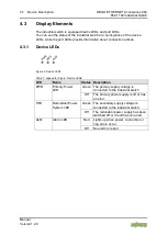
Check whether the power LED “PWR” on the top of the device lights up
when power is supplied to the device. If not, check to ensure that the power
cable is plugged in correctly and fits securely.
5.
RPS +/-:
To connect or disconnect the conductors, actuate the spring in the female
connector directly using a screwdriver or an operating tool and insert or
remove the conductor.
6.
Check whether the power LED “RPS” on the top of the device lights up
when power is supplied to the device. If not, check to ensure that the power
cable is plugged in correctly and fits securely.

