38 Mounting
Compact Power
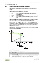
787-1211 DC power supply, 12 V
Manual
Version 1.
1
.0
P o s :
4 4
/A lle S e rie n ( A llg e m ein e M o d ule ) /Ü b er sc h rif te n /E be n e 1 /M o nt ie re n - Ü
b e rs c hr ift 1 @ 3\ m od _ 1 22 5 44 6 74 4 75 0 _ 21 .d o cx @ 2 49 0 0 @ 1 @ 1
4
Mounting
P o s :
4 5 . 1 /A lle S e rie n ( A llg e m ein e M o d ule ) /S ic h er he it s- u n d so n st ig e H
in w e is e /A ch tu n g /A ch tu n g : E le k tro s ta tis c he E n tla d u ng v e rm e id en ! @ 6 \ m od _ 12 6 01 8 1 36 4 72 9 _2 1 .d o cx @ 46 7 5 9 @ @ 1
Avoid electrostatic discharge!
The devices are equipped with electronic components that may be destroyed by
electrostatic discharge when touched. Please observe the safety precautions
against electrostatic discharge per DIN EN 61340-5-1/-3. When handling the
devices, please ensure that environmental factors (personnel, work space and
packaging) are properly grounded.
P o s : 4 5 . 2 /S e rie 7 8 7 (E P S IT R O N
) /Ü b e rs ch rif te n /E in b au la g en - Ü b er sc h rif t 2
@ 1 9 \m o d_ 1 40 3 68 4 7 10 1 14 _ 21 .d o cx @ 1 56 5 1 1 @ 2 @ 1
4.1
Mounting Positions
P o s : 4 5 . 3 /S e rie 7 8 7 (E P S IT R O N
) /M o n tie re n /M o n ta ge 7 8 7- 1 2x x - Allg e m e in E in le it u ng @ 1 8\ m od _ 13 9 3 40 3 39 7 33 5 _ 21 .d o cx @ 1 46 4 99 @ @ 1
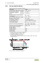
Install the device vertically to ensure proper heat dissipation (ventilation slots
above and below).
The following values should not be exceeded when installing with the front panel
at the top or bottom:
P o s : 4 5 . 4 /S e rie 7 8 7 (E P S IT R O N
) /M o n tie re n /M o n ta ge 7 8 7- 1 2x 1 - A llg em ein Ta b elle We rt e fü r F r on tp la tt e ob e n - m it D oc -V a ria b le n @ 31 \m o d _1 5 2 34 5 29 7 51 3 3_ 2 1 .d oc x @ 48 1 33 9 @ @ 1
Table 26: Values for Mounting Position – Mounting w ith Front Panel at Top or Bottom
Device
Output power
Ambient operating
temperature
787-1211
50 %
55 °C
P o s : 4 5 . 5 /S e rie 7 8 7 (E P S IT R O N
) /M o n tie re n /M o n ta ge 7 8 7- xx x x - A llg e m e in A b w eic h e nd e E in b au la g en @ 1 9\ m o d_ 1 40 3 68 4 4 74 1 41 _ 21 .d o cx @ 1 56 5 08
@ @ 1
Other mounting positions should only be used at one‘s own risk!
P o s : 4 5 . 6 /S e rie 7 8 7 (E P S IT R O N
) /Wic h tig e E r lä ut er un g e n/ Sic h e rh e its - un d s on s tig e H in w eis e /H in w e is /H in w e is: M in d e st ab s tä nd e e in ha lt en ! @ 1 9 \m o d _1 4 03 6 84 8 0 31 3 2_ 2 1. do c x @ 1 5 65 1 4 @ @ 1
Observe minimum distances!
Observe the specified minimum distances to prevent functional faults (see
section “Device Description” > “Technical Data”).
P o s : 4 5 . 7 /S e rie 7 8 7 (E P S IT R O N
) /M o n tie re n /M o n ta ge 7 8 7- 1 2x x - M on ta g em ög lic h ke it en @ 1 8\ m o d_ 1 39 3 40 3 5 04 6 38 _ 21 .d o cx @ 1 46 5 02
@ @ 1
The device can be mounted on a DIN 35 rail or with screws.
P o s : 4 5 . 8 /D o ku m e nt at io n allg e m e in /G lie d e ru n g se le m e nt e/ --- S eit e nw e c hs e l-- - @ 3 \m o d _1 2 21 1 0 80 4 50 7 8_ 0 .d o cx @ 21 8 1 0 @ @ 1


