Serie 750, 753
Planning
System manual | Version: 3.0.2
37
1
2
U
S
U
F1
U
F2
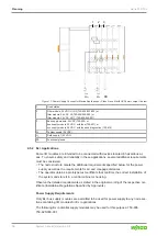
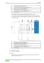
Figure 18: Ex i Power Supply Concept
1
Ex i bus supply module (750-606, 750-625/000-001)
*
2
Ex i I/O modules
U
S
System supply (24 VDC)
U
F1
Field supply 1 (24 VDC)
U
F2
Field supply 2 (24 VDC)
*)
750-606 with electronic fuse and diagnostics
750-625/000-001 with electronic fuse and no diagnostics
Clearance and Creepage Distance Requirements
For all sections of a node that contain I/O modules for Ex i use, stricter requirements re-
garding clearances and creepage distances apply. Before the first such node section, the
respective
Ex i supply module
(750-606 or 750-625/000-001) ensures the required dis-
tance.
After each such node section,
four distance modules
(750-616) must be used. This also
applies when the next section also starts with an
Ex i supply module
(750-606 or
750-625/000-001).
Exceptions:
If the following section consists of an
end module for bus extension
(750-627),
one
distance module
(750-616) is sufficient.


