Manual
WAGO-I/O-SYSTEM 750 XTR
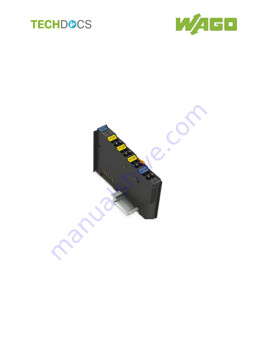
750-563/040-000
2AO 0/4-20mA/ 6-18V DC/ 16Bit /XTR
2-Channel Analog Output Module
;
0/4 ... 20 mA / 6 ...
18 VDC, 16-bit, Configurable /XTR
Version 1.3.0
Страница 1: ...Manual WAGO I O SYSTEM 750 XTR 750 563 040 000 2AO 0 4 20mA 6 18V DC 16Bit XTR 2 Channel Analog Output Module 0 4 20 mA 6 18 VDC 16 bit Configurable XTR Version 1 3 0...
Страница 2: ...87 84 45 55 E Mail support wago com Every conceivable measure has been taken to ensure the accuracy and completeness of this documentation However as errors can never be fully excluded we always appr...
Страница 3: ...vice Precautions 12 3 Device Description 15 3 1 View 17 3 2 Connectors 18 3 2 1 Data Contacts Local Bus 18 3 2 2 Power Jumper Contacts Field Supply 19 3 2 3 CAGE CLAMP Connectors 20 3 3 Display Elemen...
Страница 4: ...50 5 2 Inserting and Removing Devices 51 5 2 1 Inserting the I O Module 51 5 2 2 Removing the I O Module 52 6 Connect Devices 54 6 1 Connecting a Conductor to the CAGE CLAMP 54 6 2 Connection Examples...
Страница 5: ...XTR and in the manual for the used fieldbus coupler controller Consider power layout of the WAGO I O SYSTEM 750 XTR In addition to these operating instructions you will also need the system descriptio...
Страница 6: ...y Indicates a moderate risk potentially hazardous situation which if not avoided could result in death or serious injury Personal Injury Indicates a low risk potentially hazardous situation which if n...
Страница 7: ...otes about this Documentation 7 750 563 040 000 2AO 0 4 20mA 6 18V DC 16Bit XTR Manual Version 1 3 0 Additional Information Refers to additional information which is not an integral part of this docum...
Страница 8: ...and data files are marked in italic type e g C Program Files WAGO Software Menu Menu items are marked in bold letters e g Save A greater than sign between two names means the selection of a menu item...
Страница 9: ...nvironments All changes to the coupler or controller should always be carried out by qualified personnel with sufficient skills in PLC programming 2 1 3 Use of the 750 Series in Compliance with Underl...
Страница 10: ...aired by the user The following actions will result in the exclusion of liability on the part of WAGO Kontakttechnik GmbH Co KG Repairs Changes to the hardware or software that are not described in th...
Страница 11: ...f electrical and electronic equipment can be harmful to the environment and human health 2 1 4 1 2 Packaging Packaging contains materials that can be reused PPWD 94 62 EU and 2004 12 EU packaging guid...
Страница 12: ...tection against contact Prevent fire from spreading outside of the enclosure Offer adequate protection against UV irradiation Guarantee mechanical stability Restrict access to authorized personnel and...
Страница 13: ...evice Replace defective or damaged devices Replace defective or damaged device module e g in the event of deformed contacts Protect the components against materials having seeping and insulating prope...
Страница 14: ...electrostatic discharge per DIN EN 61340 5 1 3 When handling the devices please ensure that environmental factors personnel work space and packaging are properly grounded Use only direct current DC f...
Страница 15: ...vices Connection Example s The operational readiness and the trouble free local bus communication of the channels are indicated via a green function LED A red error LED indicates a short circuit or ov...
Страница 16: ...ally isolated and will be transmitted with a resolution of 16 bits Mixed operation Mixed operation standard XTR modules within a node is possible when groups of modules are electrically isolated on th...
Страница 17: ...end for Figure View Pos Description Details See Section 1 Marking possibility with Mini WSB 2 Status LEDs Device Description Display Elements 3 Data contacts Device Description Connectors 4 CAGE CLAMP...
Страница 18: ...which are available as self cleaning gold spring contacts Figure 2 Data Contacts Do not place the I O modules on the gold spring contacts Do not place the I O modules on the gold spring contacts in o...
Страница 19: ...s Figure 3 Power Jumper Contacts Table 4 Legend for Figure Power Jumper Contacts Contact Type Function 1 Spring contact Potential transmission Uv for field supply 2 Spring contact Potential transmissi...
Страница 20: ...nalog output 2 AO 2 5 Analog output 2 Sense AO 2 6 Positive sense connection for analog output 2 Sense AO 2 7 Negative sense connection for analog output 2 Common ground 8 Common ground for analog out...
Страница 21: ...lements Table 6 Legend for Figure Display Elements Channel Designation LED State Function 1 RUN A Off Local bus timeout Green Local bus OK ERROR C Off No group error Red Group error 2 RUN E Off Local...
Страница 22: ...22 Device Description WAGO I O SYSTEM 750 XTR 750 563 040 000 2AO 0 4 20mA 6 18V DC 16Bit XTR Manual Version 1 3 0 3 5 Schematic Diagram Figure 6 Schematic Diagram...
Страница 23: ...ion power jumper contact typ 24 VDC 5 mA 55 mA Max voltage via power jumper contacts under laboratory conditions for ambient operating temperature 40 C 55 C for ambient operating temperature 55 C 70 C...
Страница 24: ...yp 5 ms Recovery time typ 300 s Output slew rate typ 1 V s respectively 1 6 mA s Measuring error at 25 C 0 05 of full scale value Temperature coefficient 100 ppm Depending on external load impedance I...
Страница 25: ...s Surrounding air temperature operation 40 C 70 C Surrounding air temperature storage 40 C 85 C Relative humidity 95 Elevation above sea level without temperature derating with temperature derating ma...
Страница 26: ...anted to 750 563 040 000 I O modules Conformity Marking UL508 Korea Certification MSIP REM W43 AOM750 The following Ex approvals have been granted to 750 563 040 000 I O modules CULUS ANSI ISA 12 12 0...
Страница 27: ...rical equipment Equipment requirements in the types of protection EN 60079 7 2015 Electrical equipment in e type of protection with ec level of protection EN 60079 15 2010 Electrical equipment in the...
Страница 28: ...1000 shocks per axis and direction half sine EN 50155 EN 61373 Random vibration Category 1 classes A and B Shock 5g 30 ms Category 1 classes A and B Environmental Requirements EN 61850 3 Achieved EN 6...
Страница 29: ...IEEE C37 90 1 4 kV Surge Voltage Surge EN 61000 4 5 EN 60255 26 1 kV conductor conductor 2 kV conductor ground Conducted Disturbances Induced by High frequency Fields EN 61000 4 6 EN 60255 26 10 V 150...
Страница 30: ...ections EN 61000 4 17 EN 60255 26 15 Damped Oscillatory Waves EN 61000 4 18 EN 60255 26 IEEE C37 90 1 1 25 kV conductor conductor 2 5 kV conductor ground Voltage Dips Short term Interruptions and Volt...
Страница 31: ...Hz 6 GHz 60 dB V m AV 3 GHz 6 GHz Shipbuilding Class B 80 dB V m 50 dB V m QP 150 kHz 300 kHz 50 dB V m 34 dB V m QP 0 3 MHz 30 MHz 54 dB V m QP 30 MHz 2 GHz 24 dB V m QP 156 MHz 165 MHz Shipbuilding...
Страница 32: ...for EMC A or EMC B Table 20 Standards and Rated Conditions for Rail Applications EN 50155 Class Standard Compliance 4 1 Rated Operating Conditions 4 1 1 Altitude above sea level AX EN 50125 1 4 1 2 Am...
Страница 33: ...eldbus coupler controller is options i e access or evaluation of the status information depends on the respective fieldbus system Table 21 Overview of Input Output Data Input Data Output Data S0 Statu...
Страница 34: ...ut driver error 1 COM 1 Output driver error 1 COM present LOAD_1 Output driver error 2 LOAD channel 1 load error This bit is set if there is a short circuit during voltage output or if there is an ope...
Страница 35: ...ver error 1 COM channel 2 common mode overrange This bit is set if the 24V field power falls below 20 V 0 No output driver error 1 COM 1 Output driver error 1 COM present LOAD_2 Output driver error 2...
Страница 36: ...16383 10 0 7FFF 32767 15 0 BFFF 49151 20 0 FFFF 65535 Table 28 Process Values 4 mA 20 mA Data Format 0 65535 Manufacturer calibration without user scaling 4 mA 20 mA IA mA Numeric value hexadecimal de...
Страница 37: ...t in the range from 0 65535 see table Example 1 Twos complement Lower limit 10 Underrange limiting value 32758 Upper limit 10 Overrange limiting value 32778 Example 2 Leading sign amount Lower limit 1...
Страница 38: ...ng flowchart provides an overview of the stepwise processing of the input value Figure 7 Conversion Algorithm 4 4 1 Step 1 Read XIN Process Data XIN is transmitted to the module with the process data...
Страница 39: ...s less than 4 mA can be generated with negative process data values The calculation for the user scaling is carried out module internally in the 32 bit number range When user scaling is used the requi...
Страница 40: ...the entry of the limiting values If in addition a number notation in the range is selected the limiting values must be converted into equivalent values for a positive number range 4 4 5 Step 5 YDAC Ca...
Страница 41: ...ialog is divided into the following areas Title bar with position and item number of the selected I O module Information area including item number name as well as version number and version date of t...
Страница 42: ...splays the default dialog for opening files Save Saves the current parameter in a parameter file WAGO I O CHECK displays the default dialog for saving files Read Reads the current parameters of the se...
Страница 43: ...opens a page for setting the process data Channel 2 opens a tree structure with settings offset gain and process data for channel 2 Settings opens a page where settings e g operating mode number forma...
Страница 44: ...goes away the Write button is grayed out again The Process Data page displays information about the process value of the I O module and displays status messages 4 5 2 1 Settings Page Figure 11 Settin...
Страница 45: ...750 ms 1 sec 2 sec Maintain limiting values OFF Setting of the overrun limitation ON Lower limiting value 0 65535 Setting of the lower limiting value underrange limit UNR Upper limiting value 0 65535...
Страница 46: ...st be taken into account for the entry of the limiting values If in addition a number notation in the range is selected the limiting values must be converted into equivalent values for a positive numb...
Страница 47: ...tion is switched on automatically ON If the user calibration is switched on the manufacturer calibration is switched off automatically Offset 0 65535 Setting of the offset of the user calibration Gain...
Страница 48: ...Process Data page e g output stage errors supply or limiting value exceeded You can set the value via the Process Value field as follows Table 37 Setting the Process Value Menu Item Description Input...
Страница 49: ...eral No error COM Output driver error COM present Power supply Field voltage too low 24 V field voltage OK 24 V field voltage too low Local bus voltage too low 5 V system voltage OK 5 V system voltage...
Страница 50: ...cts are sharp edged Handle the I O module carefully to prevent injury Do not touch the blade contacts Insert I O modules only from the proper direction All I O modules feature grooves for power jumper...
Страница 51: ...ork when devices are energized High voltage can cause electric shock or burns Switch off all power to the device prior to performing any installation repair or maintenance work Temperature range appli...
Страница 52: ...arrier rail Figure 15 Snap the I O Module into Place Example With the I O module snapped in place the electrical connections for the data contacts and power jumper contacts if any to the fieldbus coup...
Страница 53: ...ounting 53 750 563 040 000 2AO 0 4 20mA 6 18V DC 16Bit XTR Manual Version 1 3 0 Figure 16 Removing the I O Module Example Electrical connections for data or power jumper contacts are disconnected when...
Страница 54: ...d to each CAGE CLAMP Do not connect more than one conductor at one single connection If more than one conductor must be routed to one connection these must be connected in an up circuit wiring assembl...
Страница 55: ...which are equipped with shield clamps Only then can you ensure that the accuracy and interference immunity specified for the respective I O module can be achieved even in the presence of interference...
Страница 56: ...2 hazardous areas and shall be used in accordance with the marking and installation regulations The following sections include both the general identification of components devices and the installatio...
Страница 57: ...0 000 2AO 0 4 20mA 6 18V DC 16Bit XTR Manual Version 1 3 0 7 1 Marking Configuration Examples 7 1 1 Marking for Europe According to ATEX and IECEx Figure 20 Marking Example According to ATEX and IECEx...
Страница 58: ...IC Explosion group of dust T135 C Max surface temperature of the enclosure without a dust layer Dc Equipment protection level EPL Mining I Equipment group Mining M2 Category High level of protection E...
Страница 59: ...s 59 750 563 040 000 2AO 0 4 20mA 6 18V DC 16Bit XTR Manual Version 1 3 0 Figure 22 Marking Example for Approved Ex i I O Module According to ATEX and IECEx Figure 23 Text Detail Marking Example for A...
Страница 60: ...dust layer Dc Equipment protection level EPL Mining I Equipment Group Mining M2 M1 Category High level of protection with electrical circuits which present a very high level of protection Ex Explosio...
Страница 61: ...States of America NEC and Canada CEC Figure 24 Marking Example According to NEC Figure 25 Text Detail Marking Example According to NEC 500 Table 41 Description of Marking Example According to NEC 500...
Страница 62: ...ment protection level EPL Associated apparatus with intrinsic safety circuits for use in Zone 20 IIC Group T4 Temperature class Gc Equipment protection level EPL Figure 27 Text Detail Marking Example...
Страница 63: ...mark nA Type of protection ia IIIC Type of protection and equipment protection level EPL Associated apparatus with intrinsic safety circuits for use in Zone 20 IIC Group T4 Temperature class Gc Equipm...
Страница 64: ...ting when replacing components The product is an open system As such the product must only be installed in appropriate enclosures or electrical operation rooms to which the following applies Can only...
Страница 65: ...in particular Operating DIP switches coding switches or potentiometers Replacing fuses Wiring connecting or disconnecting of non intrinsically safe circuits is only permitted in the following cases T...
Страница 66: ...telephone networks or telecommunication cables WARNING The radio receiver module 750 642 may only be used to connect to external antenna 758 910 WARNING Product components with fuses must not be fitte...
Страница 67: ...I O Module Example 53 Figure 17 Connecting a Conductor to a CAGE CLAMP 54 Figure 18 Connection Example with Sense 55 Figure 19 Connection Example without Sense 55 Figure 20 Marking Example According...
Страница 68: ...29 Table 19 EMC Emission of Interference 31 Table 20 Standards and Rated Conditions for Rail Applications EN 50155 32 Table 21 Overview of Input Output Data 33 Table 22 Overview of Input Output Data O...
Страница 69: ...00 2AO 0 4 20mA 6 18V DC 16Bit XTR Manual Version 1 3 0 Table 43 Description of Marking Example for Approved Ex i I O Modules According to NEC 506 62 Table 44 Description of Marking Example for Approv...
Страница 70: ...WAGO Kontakttechnik GmbH Co KG Postfach 2880 D 32385 Minden Hansastra e 27 D 32423 Minden Phone 49 571 887 0 Fax 49 571 887 844169 E Mail info wago com Internet www wago com...