background image

GB

16

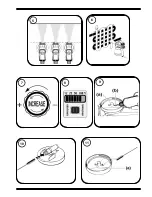
Measuring the Viscosity

Dip the viscosity test cup 

(Illus. 

)

completely into the spray material. Hold the test cup

up and measure the time (in seconds) until the liquid empties out. Compare the 
measured "runout time" with the handling table for viscosity.

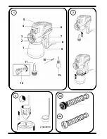
Valve data (handling table page 15)

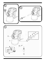
The nozzle can be removed using the nozzle spanner. The valve is behind the nozzle
and comprises:

1. Atomizer head
2. Spring
3. Valve taper

Standard

Valve with black atomizer /(stronger spring) - lacquer valve (Illus. 4 a)

Suitable for substances containing solvents and water-diluted paints. The use of this 
valve optimises spraying results at reduced delivery rate - electronic settings 50 %, 
25 % oder 12 %. 
For details refer to handling table page 15.

● 

Enclosed valve with white atomizer (weaker spring, softer valve cone) - 

plastic-emulsion and latex-paint valve. (Illus. 4 b)

Suitable for water-thinned paints - valve cone more resistant to wear. Use with 
maximum delivery rate - electronic setting 100 %. 
For details refer to handling table page 15.

Start-up

1.

Cover areas that are 

not

to be sprayed. When woriking keep in mind that wind, for

example, may transport paint mist over great distances and cause damage.

2. Before connecting to the mains supply, please be sure that the supply voltage is

identical with the value given on the rating plate (on the side of the spray gun).

3. Dilute the spray material according the handling table (page 15).
4. Place the container on a sheet of paper and fill it with the prepared spray material.

Attention! Do not operate the spray gun without spray material in the 

container; this can lead to increased wear of the pump!

5. Position the spray gun on the container and turn the container to the right until the

container fits tightly 

(Illus. 

, arrow)

.

6. Activate the switch to start up the spray gun. First the spray gun sucks in spray 

material, then after a few seconds the material emerges from the nozzle. To 
accelerate the intake, turn the fine adjustment button to maximum.

7. By turning the fine adjustment button you can vary the spray amount 

(Illus. 

, arrow)

.

Note:

Regulating with the fine adjustment button influences the spray pattern 
depending on the spray material and the degree of dilution.

W 450 SE

Содержание W450 SE

Страница 1: ...W 450 SE D GB F NL 2 Jahre Garantie 2 years guarantee 2 ans de garantie 2 jaar garantie...

Страница 2: ...3 0209058 2 1 12 7 8 9 6 5 4 3 2 1 10 13 11 4a 4b...

Страница 3: ...10 11 6 7 5 8 9...

Страница 4: ...14 13 12 8 4 5 6 7 3 11 10 9 1 2...

Страница 5: ...contain flammable liquids gases or dusts Power tools generate sparks that can ignite the dust or vapors c Keep children and other persons away when using the power tool You can lose control of the to...

Страница 6: ...h or if you connect the power tool to the power supply which it is on d Remove setting tools or wrenches before switching on the power tool A tool or wrench that is in a rotating tool part can lead to...

Страница 7: ...l function is impaired Have damaged parts repaired before using the tool Many accidents have their origin in power tools that have been maintained badly f Keep the cutting tools sharp and clean Cuttin...

Страница 8: ...res smoke of lit cigarettes cigars and tobacco pipes sparks glowing wires hot surfaces etc in the vicinity during spraying The spray gun is not a toy children must therefore not be allowed to handle i...

Страница 9: ...ith the spray gun You will find guidelines for sprayable dilutions in the following handling table for viscosity viscosity consis tency of the paint You can achieve the correct dilution by using the v...

Страница 10: ...table page 15 Start up 1 Cover areas that are not to be sprayed When woriking keep in mind that wind for example may transport paint mist over great distances and cause damage 2 Before connecting to t...

Страница 11: ...should always be immersed in li quid If air is sucked in larger drops may result When spraying hold the spray gun in a horizontal position Use the flexible nozzle extension Illus special accessories f...

Страница 12: ...l soiled parts Illus 6 Reassemble the parts in reverse order 7 Put a few drops of oil e g sewing machine oil in the intake and runback holes Illus arrow Briefly switch on the spray gun Environmental p...

Страница 13: ...mp Insert valve Suction tube loose in the conical bore Adjust suction tube Venting hole in pump housing clogged Clean Intake hole fitting in pump housing logged Clean Viscosity of spray material too h...

Страница 14: ...arge replacement of the defective parts The guarantee does not cover incorrect use or commissioning or fitting or repair work which is not stated in our operating instructions Wearing parts are also e...

Страница 15: ...your plug proceed as follows Should the moulded plug have to be replaced never re use the defective plug or attempt to plug it into a different 13 A socket This could result in an electric shock Shou...

Страница 16: ...4 1 2002 EN 55014 2 2001 EN 61000 3 2 2005 EN 61000 3 3 2001 CE D claration de conformit Nous d clarons sous notre responsabilit que ce produit est en conformit avec les r glementations suivantes 73 2...

Страница 17: ...erviamo cambiamenti Ret til aendringer forbeholdt Salvo modificationes Wagner Spraytech Benelux B V Zoonebaan 10 3542 EC Utrecht Wagner Spraytech Belgie Veilinglaan 58 1861 Meise Wolvertem Magyarorsz...

Отзывы: