


P20
9
GB
Spraying Technique
1
2
4
5
3
4.4
Taking the unit into operation with coating
material
1. Immerse the suction tube (Fig. 4, Item 2) and return hose (1)
into the coating material container.
2. Turn the pressure control knob counterclockwise (3) to
minimum pressure.
3. Open the relief valve (4), valve position PRIME
(
k
circulation).
4. Switch the unit (5) ON.
5. Wait until the coating material exudes from the return hose.
6. Close the relief valve, valve position SPRAY (
p
spray).
7. Trigger the spray gun several times and spray into a collecting
container until the coating material exits the spray gun
without interruption.
8. Increase the pressure by slowly turning up the pressure
control knob.
Check the spray pattern and increase the pressure until the
atomization is correct.
Always turn the pressure control knob to the lowest setting
with good atomization.
9. The unit is ready to spray.
5.
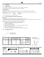
Spraying technique
Injection hazard. Do not spray without the tip guard
in place. NEVER trigger the gun unless the tip is
completely turned to either the spray or the unclog
position. ALWAyS engage the gun trigger lock
before removing, replacing or cleaning tip.
The key to a good paint job is an even coating over the entire surface.
Keep your arm moving at a constant speed and keep the spray gun at
a constant distance from the surface. The best spraying distance is 25
to 30 cm between the spray tip and the surface.
25 - 30 cm
Keep the spray gun at right angles to the surface. This means moving
your entire arm back and forth rather than just flexing your wrist.
Keep the spray gun perpendicular to the surface, otherwise one end
of the pattern will be thicker than the other.
Trigger gun after starting the stroke. Release the trigger before
ending the stroke. The spray gun should be moving when the trigger
is pulled and released. Overlap each stroke by about 30%. This will
ensure an even coating.
25 - 30 cm
25 - 30 cm
i
If very sharp edges result or if there are streaks in the
spray jet – increase the operating pressure or dilute
the coating material.


