44
Super Finish 33 PLUS/PRO • Nespray Pro
3.5
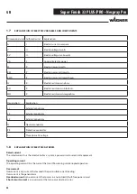
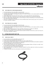
REPLACING THE EARTHING CONTACT SOCKET
1. Ensure safe isolation from the supply before commencing work.
2. Loosen the fastening screws and remove the socket from the housing.
3. Loosen and remove all cables at the earthing contact socket, noting the contact confi guration.
4. Establish the electrical connection to the new earthing contact socket, ensuring correct and safe contacting.
5. The earthing contact socket can now be re-installed in the housing.
Pay attention to the installation position of the socket. This must ensure the best possible splash protection, even in opera-
ting status.
6. After completing the repair a measurement in accordance with BGV A3 must be carried out, in order to ensure electrical
safety and functionality.
7. The defective component must be made inoperative in order to prevent further use.
3.6
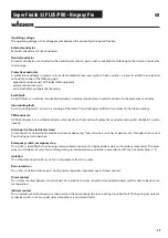
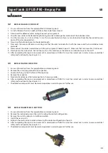
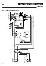
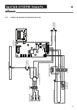
REPLACING THE MOTOR PROTECTING SWITCH
1. Ensure safe isolation from the supply before commencing work.
2. Mark the individual wires with the relevant terminal designation of the motor protecting switch, in order to prevent mix-
up.
3. Now disconnect all electrical connections from the motor protecting switch.
4. The motor protecting switch can now be removed.
5. Now install the new motor protecting switch and restore the electrical connection.
6. After completing the repair a measurement in accordance with BGV A3 must be carried out, in order to ensure electrical
safety and functionality.
7. In order to prevent further use of the defective motor protecting switch, it must be made unserviceable and disposed of.
3.7
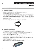
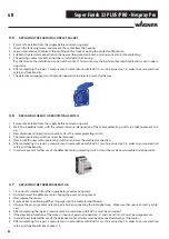
REPLACING THE THREEPHASE MOTOR
1. 1. Ensure safe isolation from the supply before commencing work.
2. First disconnect the defective motor, noting the exact pin assignment.
3. Now replace the motor.
4. Ensure correct positioning of the Y/Δ jumpers on the motor terminal board.
5. Observe the pin assignment noted in point 2 when connecting the individual wires. Make sure that secure contact is achie-
ved.
6. After completing the repair a measurement in accordance with BGV A3 must be carried out.
7. If the direction of rotation of the motor is incorrect, external conductors L1 and L2 and U and V must be swapped over.
8. In order to exclude further use of the defective motor, all wires must be disconnected directly at the motor.
9. After completing the repair a measurement in accordance with BGV A3 must be carried out, in order to ensure electrical
safety and functionality See chapter 1.4
GB
Содержание Nespray Pro
Страница 31: ...31 Super Finish 33 PLUS PRO Nespray Pro GB...

