36
HC 35 E • HC 45 E • HC 55 E
g
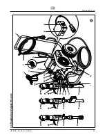
1
Spray gun
2
High-pr
essur
e hose
3
Electric motor
4
ON/OFF switch
5
Contr
ol lamp shows that the unit is r
eady
for operation HC 35 E, HC 45 E, HC 45 E-SSP
6
Unit connection line (230 V)
7
Extractable shaft
8
Contr
ol lamp shows that the unit is r
eady
for operation HC 55 E, HC 55 E-SSP
9
O
N/OFF switch (400 V)
HC 55 E, HC 55 E-SSP
10
V
-belt under the belt cover
11
Retur
n hose
12
Suction tube
13
High-pr
essur
e filter
14
Material feed pump
HC 45 E, HC 55 E
15
Material feed pump
HC 45 E-SSP
, HC 55 E-SSP
Description of unit
3.3
Explanatory diagram legend HC units
16
Material feed pump HC 35 E
17
Manometer
18
Retention pin for the swivel mechanism
19
Filling orifice for separating oil
(separating oil pr
events incr
eased wear
and tear of the packings)
20
Ball valve
lever position horizontal –
hydraulic motor switched of
f
lever position vertical –
hydraulic motor switched on
21
Handle for swiveling the material feed pump
22
Hydraulic motor
23
Relief valve knob
T
u
rn
left for cir
culation
k
T
u
rn
right for spray
p
24
Hydraulic oil pump
25
Pr
essur
e r
egulating knob
26
Oil measuring stick

