


33
VERSION 03/2018
ORDER NUMBER DOC 2369735
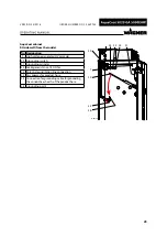
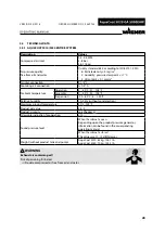
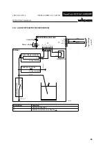
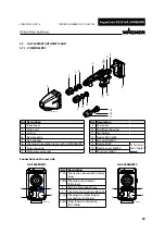
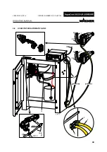
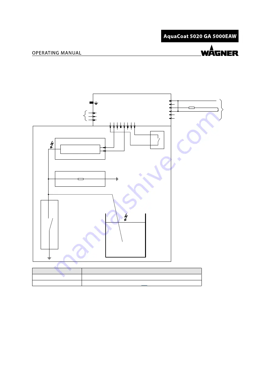
5.5.5 AQUACOAT ELECTRIC BLOCK DIAGRAM
B_05941
6
J2
J3
5
4
3
2
1
Earth mon
Dat dis
Dat sw
Earth
4
3
1
6
2
5
7 8
L
N
PE
P1
Coil +
Coil -
GND
D
oor sw
.
Er
ror out
HV in
HV out
uA out
1k2
VM 5020WA control unit
Cabinet
Gr
ounding swit
ch
Leakage resistance
Casting compound
Pneuma
tic c
ylinder
Power supply
Grounding
yellow/green
Door switch
white
High-voltage multiplier
Casting compound
yello
w/g
reen
blue
black
brown
white
Shield
H
igh v
oltage
on/off
white
Coil +
Coil -
Orange
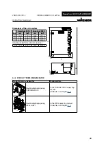
Connection
Function
J2
Control connection
J3
External interface, see Chapter


