


SYSTEM DESCRIPTION
5
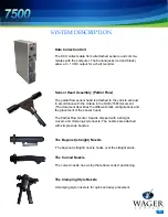
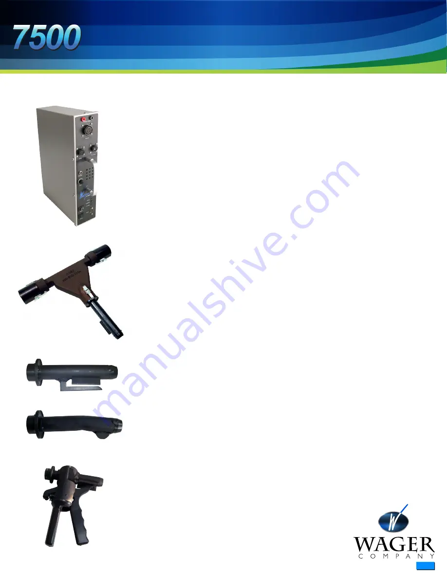
Data Collection Unit
The DCU collects data from all attached sensors and commu-
nicates with the computer. The banana jacks (red and black)
allow a 0 –1 VDC output for a chart recorder.
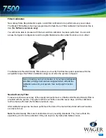
Sensor Head Assembly (Partial Flow)
The partial flow sensor head is attached to the vehicle exhaust
in accordance with the criteria in the SAE J1667 document.
(The document describes the different stack configurations and
the placement of the sensor head).
The Partial Flow Sensor Head is shipped with a straight,
curved, and clamping style nozzle. The nozzles are attached
with simple snap buckles.
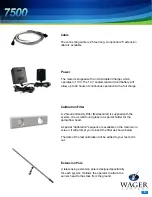
The Bayonet (straight) Nozzle
The bayonet (straight) nozzle hooks over the straight stack..
The Curved Nozzle
The curved nozzle has a stop that allows correct positioning.
The Clamping Style Nozzle
A clamping style nozzle is for quick and easy placement.
Содержание 7500
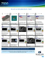
Страница 16: ...1 4 SNAP ACCELERATION TEST...
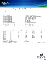
Страница 19: ...1 7 Samples of Completed Test Print Outs Snap Idle Test...
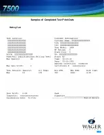
Страница 20: ...1 8 Samples of Completed Test Print Outs Rolling Test...
Страница 21: ...1 9 Samples of Completed Test Print Outs Stall Test...