background image

www.DaltonsWadkin.com

www.DaltonsWadkin.com

www.DaltonsWadkin.com

Содержание GA

Страница 1: ...l s c 1 J Cl LL ca J E C C c ls o l L s 0 J calllll I C c s Cl s c ca CI 3 0 LL a N o N ci Z J C J Z C E z o i J 0 I en z w w w D a l t o n s W a d k i n c o m www DaltonsWadkin com www DaltonsWadkin com ...

Страница 2: ...l J Cl LL ca J EGi Cl Cl C Sc o s c o I E _ c C C Cl C C ca CC ca s 3 s 0 LL C tn Cl C o E 0 o Z Z f Cl w 2 f J s tJ s c JCjJc J w w w D a l t o n s W a d k i n c o m www DaltonsWadkin com www DaltonsWadkin com ...

Страница 3: ...NY WADKIN LTD Green Lane Road Leicester LE54PF RESPONSIBLE PERSON Mr A C Lotl Managing Director MACHINE DESCRIPTION TYPE THROUGH FEED FOUR SIDE PLANING MACHINE AND MOULDER MODEL GA DIRECTIVES COMPLIED WITH Supply of Machinery Safety Regulations 1992 Amendment No 2063 1994 Draught Proposal CENITC 142 ISO 9001 Part 1 SIGNED ON BEHALF OF WADKIN PLC w w w D a l t o n s W a d k i n c o m www DaltonsWad...

Страница 4: ... Side Planing and Moulding Machine Model GA OPERATION AND MAINTENANCE MANUAL Wadkin Limited Green Lane Road Leicester LE54PF Telephone 0044 0 116 2769111 Fax 0044 0 116 2742310 w w w D a l t o n s W a d k i n c o m www DaltonsWadkin com www DaltonsWadkin com ...

Страница 5: ...PECIFICATION 2 1 3 INSTALLATION 3 1 C 3 1 Receipt of the Machine 3 1 3 2 Preparation for Installation 3 1 C 3 3 Lifting and Locating the Machine 3 1 3 4 Connecting the Services 3 2 3 4 1 Electrical Supply 3 2 0 3 4 2 Pneumatic Air Supply 3 3 3 4 3 Dust Extraction 3 3 0 4 MACHINE USAGE AND CONTROLS 4 1 4 1 Safe Practices 4 1 0 4 1 1 Pre operation Checks 4 1 4 1 2 Checks During Operation 4 1 4 1 3 S...

Страница 6: ... 7 3 7 3 1 Re tension Top Bottom Head Drive Belt 7 3 C 7 3 2 Re tension Fence Side Head Drive Belt 7 4 7 3 3 Replace Top Bottom Head Drive Belt 7 4 7 4 3 Replace Fence Side Head Drive Belt 7 4 C 7 3 5 Replace Outfeed Bottom Drive Belt on Machine fitted with Straightening Infeed Table 7 4 7 3 6 Replace Shaft Mounted Top Feed Roll 7 5 7 3 7 Replace Flange Mounted Top Feed Rolls Spacers 7 5 7 3 8 Rep...

Страница 7: ...ven Roller System 8 10 r Section Page 8 4 Push Feed System 8 11 8 5 Grooved Bed 8 12 8 6 Unit G 8 14 8 7 Intermediate Feed Roll 8 19 G GLOSSARY C C C C Q 0 0 0 C 0 U Page 3 G w w w D a l t o n s W a d k i n c o m www DaltonsWadkin com www DaltonsWadkin com ...

Страница 8: ...cepting and receiving the machine from the manufacturer Sections Two to Seven provide the information necessary to install operate and maintain the machine including procedures for fault finding At the end of the manual is a Glossary of terms used throughout the body of the manual Also depending upon any special machine features and or nature of operation Additional Equipment Appendices are includ...

Страница 9: ...of woodworking machinery in the UK These regulations are listed below and the user is advised to refer to the relevant parts of these regulations and ensure that the requirements are complied with Where the machinery is used outside the UK then the regulations of that country will apply and should be complied with Note The list below relates to the most recent published editions of the regulations...

Страница 10: ...ons on the user see Section 1 2 Woodworking Machines Regulations These regulations place absolute legal requirements on employers and users to ensure that all fitted guards and safety devices are always used securely fitted correctly adjusted and properly maintained The regulations also require that maintenance be undertaken only by suitably qualified and competent personnel and that all power sup...

Страница 11: ... shall ensure that the equipment is used for the operations for which and under the conditions for which it is suitable Other requirements include provision of suitable training of users provision of suitable documentation information and instructions and declarations of any specific risks Specific Information Section 4 of this manual Machine Usage and Controls identifies and details general safe ...

Страница 12: ...rmful to health through inhalation and also skin contact The Control of Substances Hazardous to Health Regulations place legal requirements on employers to prevent exposure of the user to substances hazardous to health or where prevention is not practicable to adequately control the exposure Adequate control should be achieved by measures other than provision of personal protective equipment The R...

Страница 13: ...ize admitted Maximum finished work size Feed speeds Pneumatic Air Requirement GA170 GA220 Refer to machine Foundation Plan Refer to the machine Specification Plate located on the machine frame 180 230mm x 130mm 170 220mm x 120mm 6 to 36m min standard 0 25 m3 min Page 2 1 w w w D a l t o n s W a d k i n c o m www DaltonsWadkin com www DaltonsWadkin com ...

Страница 14: ...d stored away from the machine Check that the following lifting equipment is available and of is of adequate capacity crane or approved lifting equipment 45mm diameter steel rods 1 2m long certified as suitable for lifting purposes lifting slings capacity according to machine Foundation Plan wooden chocks Refer to the Foundation Plan for details of the floor area required al1d for any special foun...

Страница 15: ...firmly bolted down before connecting any services Connecting the Services Electrical Supply The customer is responsible for an electrical supply suitable to meet the power requirements of the machine These requirements are shown on the machine Specification Plate on the machine frame and are also shown on the electrical schematic connection diagram accompanying the machine Electrical connections s...

Страница 16: ... be corrected by reversing any two of the incoming supply connections to the terminals of the electrical control cubicle WARNING Phase changes must be made by a competent and experienced electrician Pneumatic Air Supply The customer is responsible for a pneumatic air supply suitable to meet the requirements of the machine as shown on the machine Foundation Plan O 25m3 min The air supply connection...

Страница 17: ...ions Duct air velocities in m second Average pressure drop at machine extraction connections are shown below Duct Diameter mm 120 150 Required Air Volume m3 hour at 30m sec 1222 1909 Pressure Drop Pa 1000 850 Page 3 4 w w w D a l t o n s W a d k i n c o m www DaltonsWadkin com www DaltonsWadkin com ...

Страница 18: ...SES FOR WHICH IT WAS DESIGNED Pre operation Checks All guards and fences are fitted securely and properly adjusted to suit their purpose Dust extraction equipment is working correctly Machine controls are functioning correctly see Section 4 2 Adequate working space is provided and lighting is available Checks During Operation Proper protective equipment is available and employed goggles ear defend...

Страница 19: ...hine electrically isolate the machine The feed must be restarted at the control panel after removal of the cause of the trip 1 Figure 4 1 2 A splinter catching device protects against splinters at the machine infeed fitted when the machine is specified for splitting use If the enclosure door is opened during normal operation all spindles and feed rolls stop With the enclosure open the machine may ...

Страница 20: ...e control panel may differ slightly from the panel on the machine being installed Feed Stop Start 1 Toggle start stop button with indicator lamp which controls the operation of the feed rolls Inch Forward Reverse 2 Two buttons and a keyswitch enable the feed to be inched forward or backwards for setting up or other maintenance purposes 3 6 2 1 7 2 c L J 5 4 Figure 4 2 1 Beam Raise Lower 3 Two butt...

Страница 21: ... cutter blocks belts etc lamp indication when enabled Spindle Start Stop 7 Each spindle has a toggle start stop button with lamp indicator These enable spindles to be started and stopped independently Other optional controls not shown on Figure 4 2 1 but which can be mounted on the machine control panel include Power On Off Toggle power on off button with lamp indicator Controls power through the ...

Страница 22: ...4 2 2 2 1 3 4 Figure 4 2 2 Emergency Stop 1 Emergency stop button shuts down machine operation when depressed Must be unlocked to reset Feed Speed 2 Controls the speed of the feed through the machine Must be adjusted only when the feed is operating Air Pressure Regulators Gauges 3 Set the feedroll pressures Page 4 5 w w w D a l t o n s W a d k i n c o m www DaltonsWadkin com www DaltonsWadkin com ...

Страница 23: ...o be split into predetermined widths Infeed Nip Driven Roller System This equipment enables improved feeding of wet timber and permits timber straightening to be undertaken Push Feed System Provides additional positive feed of timber through top and bottom hydraulic feed rolls Grooved Bed Processes short lengths of twisted timber UnitG The unit G is a heavy duty splitting unit Intermediate Feed Ro...

Страница 24: ...rocedure for setting up all cutting tools is as follows 1 Place the straight edge on the table or against the fence behind the tool and hold in position 2 3 4 Rotate the tool by hand in the opposite direction of the cut Adjust the position of the tool using the crank handle until a cutting edge of the tool touches the straight edge To eliminate spindle backlash always move the bottom head and edge...

Страница 25: ...ipment required 1 Straight edge 2 Standard tool kit Remove Refit Cutter Block in Spindle Figure 5 1 2 WARNING ENSURE THAT THE MACHINE IS ELECTRICALLY ISOLATED EMERGENCY STOP ACTIVATED BEFORE PROCEEDING Notes All spindles have right hand threads 00 not strike any component do not use a box or extension spanner 2J 2 1 Page 5 2 w w w D a l t o n s W a d k i n c o m www DaltonsWadkin com www DaltonsWa...

Страница 26: ... hexagon 1 of the spindle and the two flat faces of the cutter block locknut 2 unscrew counterclockwise Remove the locking collar 3 4 Before refitting the cutter block carefully clean the spindle and the cutter block 5 Locate the cutter block on the spindle and the locking collar and tighten the hexagon clockwise using a combination spanner Page 5 3 w w w D a l t o n s W a d k i n c o m www Dalton...

Страница 27: ... Release the spindle brake 4 5 6 7 Release locking handle 2 Turn the cutter block by hand counterclockwise and using the crank handle adjust shaft 3 until a cutting edge of the cutter block just touches the straight edge The final movement of the spindle should be towards the workpiece Lock handle 2 Check that adjustment is correct across whole width of the cutter block Horizontal Setting This adj...

Страница 28: ... c c 0 ro ro E l a in c f w w w D a l t o n s W a d k i n c o m www DaltonsWadkin com www DaltonsWadkin com ...

Страница 29: ...evel with the outfeed side bed of the fence the actual cut having been set by the infeed fence adjustment see a later procedure It also sets the depth of the cutter block below the bed WARNING ENSURE THAT THE MACHINE IS ELECTRICALLY ISOLATED EMERGENCY STOP ACTIVATED BEFORE PROCEEDING 5 4 1 7 3 6 2 Figure 5 3 Page 5 6 w w w D a l t o n s W a d k i n c o m www DaltonsWadkin com www DaltonsWadkin com...

Страница 30: ...ise rotation moves it towards the fence Lock handle 2 Position outfeed fence nose piece 4 by slackening the two locking screws 5 located behind the fence and then locating the nose piece 3 to 5mm from the cutter block 8 Retighten screws 5 Vertical Setting 9 Establish depth of the cutter block below the bed and note the reading on the digital indicator 10 Release locking handle 2 and clamp 6 11 12 ...

Страница 31: ... setting of the near side head chipbreaker and the near side head pad pressure WARNING ENSURE THAT THE MACHINE IS ELECTRICALLY ISOLATED EMERGENCY STOP ACTIVATED BEFORE PROCEEDING 1 6 5 3 4 2 Figure 5 4 Horizontal Setting 1 Open or remove any guards to permit easy access and ensure that the near side head outfeed bed is clear 2 Place a datum block 1 of known width between the near side head fence a...

Страница 32: ... grubscrew Lock handle 2 Vertical Setting 8 9 10 Establish depth of the cutter block below the bed and note the reading on the digital indicator Release locking handle 2 and clamp 4 Using the crank handle adjust shaft 5 until the spindle flange is 5mm below the level of the bed The final movement of the spindle should be towards the workpiece Clockwise rotation of the crank handle raises the cutte...

Страница 33: ... the machine Check that the tip of the pad pressure shoe is between 3 and 5mm from the tip of the cutter Tighten bolts 6 Refit replace guards Page 5 10 w w w D a l t o n s W a d k i n c o m www DaltonsWadkin com www DaltonsWadkin com ...

Страница 34: ...f the beam The setting procedure when an outboard bearing support is fitted is covered at the end of this Section WARNING ENSURE THAT THE MACHINE IS ELECTRICALLY ISOLATED EMERGENCY STOP ACTIVATED BEFORE PROCEEDING Vertical Setting 1 Open or remove any guards to permit easy access and ensure that the first top head outfeed bed is clear 2 Place a datum block 1 of known height on the bed beneath the ...

Страница 35: ...te the emergency stop Turn the cutter block by hand counterclockwise and using the crank handle adjust shaft 4 until a cutting edge of the cutter block just touches the datum block The final movement of the spindle should be away from the workpiece Clockwise rotation of the crank handle lowers the cutter block towards the block giving a negative count on the digital indicator counterclockwise rota...

Страница 36: ... the vertical setting procedure is modified as follows If hydraulic locks are used on the outboard bearing then these must first be disengaged by operation of the clamp off button on the main control panel Altematively if no hydraulic locks are fitted the outboard bearing lock must be released After adjustment the hydraulic locks should be re engaged by operation of the clamp on button or the outb...

Страница 37: ...ical for both types This procedure sets the pad pressure and chipbreaker to the base cutting circle of the first top head cutter block The pneumatic option of chipbreaker is illustrated in Section 8 WARNING ENSURE THAT THE MACHINE IS ELECTRICALLY ISOLATED EMERGENCY STOP ACTIVATED BEFORE PROCEEDING 2 3 1 6 5 5 4 Page 5 14 w w w D a l t o n s W a d k i n c o m www DaltonsWadkin com www DaltonsWadkin...

Страница 38: ...duct width and tighten locknut 3 Ensure that the pad is in front of the fence line Check that the chipbreaker shoes 4 are compatible with the diameter of the cutter block Each top head is supplied with three different lengths of chipbreaker shoe to suit various diameters of cutter block Each shoe is secured by two countersunk screws through the bottom face The shoe should be as close as possible t...

Страница 39: ...ARNING ENSURE THAT THE MACHINE IS ELECTRICALLY ISOLATED EMERGENCY STOP ACTIVATED BEFORE PROCEEDING Vertical Setting 1 Open or remove any guards to permit easy access and ensure that the bottom head outfeed side bed is clear 2 Place the straight edge 1 on the outfeed side bed extending over the bottom head cutter block 3 Release locking handle 2 4 Release the spindle brake 1 4 4 2 6 Figure 5 7 Page...

Страница 40: ...r block Retighten clamps 4 8 Lock handle 2 9 Check that adjustment is correct across whole width of the cutter block Horizontal Setting 10 Release spindle barrel clamp 5 11 12 13 14 5 Figure 5 7 Using the crank handle adjust shaft 6 until the spindle flange is 5mm behind the fence line The final movement of the spindle should be towards the workpiece Tighten barrel clamp 5 Refit replace guards Che...

Страница 41: ...r buttons on the machine control panel This setting should be the height of the finished product Maximum traction over the full width of the product is achieved by using spacers f1ange mounted feed rolls and by positioning of rolls at points along the shaft shaft mounted feed rolls Feed rolls shall be fitted not less than 4mm from a fence WARNING ENSURE THAT THE MACHINE IS ELECTRICALLY ISOLATED EM...

Страница 42: ...e to the face of the end feed roll Slot the C washer 2 over the draw bolt 1 and tighten the draw bolt 1 2 Figure 5 8 2 Setting Feed Rolls after the Top Head Figure 5 8 3 This procedure is undertaken after the beam control setting and the setting should be approximately 3mm less than the finished product height 1 Slacken nut 1 2 3 Rotate handwheel 2 to adjust the height of the feed roll from the be...

Страница 43: ...e the timber beneath the top roller assembly 2 Slacken bolt 2 and position the roller as close as possible to the cutter block 3 Slacken bolt 3 and move the roller laterally to be central to the cutter block 4 Slacken bolt 4 and lower the roller until it touches the timber 5 Rotate screw 5 to increase or decrease pressure on the roller 6 Tighten bolts 2 3 and 4 Page 5 20 w w w D a l t o n s W a d ...

Страница 44: ...Each type has a dedicated adjustment procedure WARNING ENSURE THAT THE MACHINE IS ELECTRICALLY ISOLATED EMERGENCY STOP ACTIVATED BEFORE PROCEEDING Straightening Infeed Table Adjustment 1 Rotate knurled handle 1 counterclockwise to release locking mechanism 2 Position handle until the indicator 2 reads the required cut depth 3 Rotate handle 1 clockwise to lock the table 1 5 6 2 7 Figure 5 9 Short I...

Страница 45: ...oth types ofinfeed table 1 2 Rotate handle 5 counterclockwise to release locking mechanism Using handle 6 adjust the infeed fence until the scale 7 reads the required measurement 3 Rotate handle 5 clockwise to lock the infeed fence Page 5 22 w w w D a l t o n s W a d k i n c o m www DaltonsWadkin com www DaltonsWadkin com ...

Страница 46: ...and Adjustments 1 2 3 Close the electrical supply isolator and connect the pneumatic air supply at the electrical control cubicle Power up the machine at the main control panel Position the near side head chipbreaker and pad pressure to the width of the finished product see Section 5 4 4 Set the first top head to the height of the finished product see Section 5 5 5 Lower the beam to the height of ...

Страница 47: ...imber should be carried out at each position and at this point if necessary adjustments of cut pressure etc should be undertaken WARNING ALWAYS ELECTRICALLY ISOLATE THE MACHINE BEFORE EACH AND EVERY ADJUSTMENT DURING A TEST PIECE PROCEDURE Repeat Step 9 until the test piece timber meets all dimensional and quality requirements Set the machine to operate in production mode by setting the enclosure ...

Страница 48: ...ator unscheduled maintenance must be undertaken by an engineer experienced on this type of equipment and equipped with special tools Scheduled Maintenance The following schedule when undertaken should be recorded in a maintenance log Equipment required 1 Compressed air gun 2 Standard tool kit 3 Lubricants as detailed 4 Grease gun 5 Oil hand pump 6 Replacement parts as necessary Daily WARNING ENSUR...

Страница 49: ...machine is fitted with centralised lubrication 2 3 Apply hydraulic oil using a hand pump via the lubrication points on the front of the machine see the lubrication chart at the end of this Section for oil types If the machine is manually lubricated Grease the machine slideways and handscrew mechanisms with lithium grease using a grease gun via the grease nipples on the front and at the rear of the...

Страница 50: ...ll be times depending upon the work to be undertaken where many of these procedures will be carried out sequentially Equipment required 1 Standard tool kit 2 Hexagonal key 3 Replacement parts as necessary WARNING ENSURE THAT THE MACHINE IS ELECTRICALLY AND PNEUMATICALLY ISOLATED BEFORE UNDERTAKING ANY OF THE FOLLOWING TASKS ENSURE THAT PROPER PROTECTIVE CLOTHING IS USED THROUGHOUT THESE TASKS Re t...

Страница 51: ...ouches the motor rim Tighten bottom nut 2 6 Tighten top nut 2 7 Tighten the four nuts 1 When slackening the drive belt reverse Steps 3 and 4 Re tension Fence Side Head Drive Belt Figure 7 3 2 1 Slacken locking nut 1 2 Screw adjusting bolt 2 counterclockwise until pressure is removed from pivot plate 3 3 Screw nut 1 10mm away from the mounting bracket Screw in bolt 2 until nut 1 contacts the mounti...

Страница 52: ...move the belt and replace with a suitable bell 4 Tighten nut 1 5 Tension the belt as described in Section 7 3 2 Replace Outfeed Bottom Drive Belt on Machine fitted with Straightening Infeed Table Figure 7 3 51 1 Remove the belt cover 1 2 Remove the two grub screws 2 using an hexagonal key 3 4 5 Insert one of the grub screws into jacking hole 3 Screw in the grub screw until bush 4 is loosened Remov...

Страница 53: ...ry ie main feed drive belt infeed drive belt and outfeed drive belt machine with short infeed table it is recommended that Wadkin is contacted owing to the complexity of the work to be undertaken For supply and information of all drive belts contact Wadkin Service Department Page 7 6 w w w D a l t o n s W a d k i n c o m www DaltonsWadkin com www DaltonsWadkin com ...

Страница 54: ...screw 1 1 Figure 7 3 6 Replace Flange Mounted Top Feed Rolls Spacers Figure 7 3 7 1 Slacken the draw bolt 1 remove the C washer 2 and withdraw the bolt 2 3 Dismantle spacers and feed rolls from the draw bolt 1 2 Figure 7 3 7 Fit new spacers and feed rolls over the draw bolt engaging drive pins of spacers and feed rolls into opposite holes The combination of feed rolls and spacers will depend upon ...

Страница 55: ...he shaft until the digital indicator reads zero see Figures 5 2 5 5 or 5 7 depending upon the head spindle being replaced At this position the spindle shoulder and the reference fence should be in line 3 Remove the drive belt see Section 7 3 3 4 Slacken the spindle barrel clamp 1 Insert a wedge into the clamp housing 2 to help release of the spindle 5 Slacken the axial adjustment clamp ring at the...

Страница 56: ...d the axial clamp 11 Ensure that the spindle rotates freely 12 Fit the drive belt see Section 7 3 3 and tension see Section 7 3 1 13 Fit the cutter block see Section 5 1 2 Replace Fence Near Side Head Spindle Figure 7 3 9 1 Reinstate the electrical and air supplies to the machine and raise the beam to its fullest extent 2 Isolate the electrical and air supplies before progressing further 3 Remove ...

Страница 57: ...pwards from its housing and place in a clean area Before fitting a new or refurbished spindle ensure that the spindle and clamp housings are clean Smear the inside face of the spindle bore with hydraulic oil and before inserting the spindle spray the barrel with a graphite grease see the lubrication chart at the end of this Section for oil grease types Lower and locate the spindle so that the shou...

Страница 58: ...ied on the product after processing with an indication of the diagnosis and remedy FAULT Blips at leading end of underside of product Diagnosis Remedy Cutter block set too low in relation to bedplate Adjust cutter block FAULT Blips on trailing end of underside of product Diagnosis Remedy Cutter block set too high in relation to bedplate Adjust cutter block FAULT Trailing end of product top face sh...

Страница 59: ...the machine FAULT A spindle motor or feed motor does not start Diagnosis Remedy Circuit breaker out Reset circuit breaker Motor fuse blown Check fuse and replace Motor contactor failed Check contactor for pitted contacts or mechanical failure Open circuit in motor line leads Check circuit and correct If fuse or circuit breaker fault re occurs investigate for cause on the motor FAULT Motor contacto...

Страница 60: ...motor line leads Check circuit and correct FAULT Motor noisy when running Diagnosis Remedy Establish if mechanical or electrical problem If mechanical noise will change in intensity frequency with change in motor speed if electrical noise will continue after motor has stopped Carry out appropriate investigation FAULT Spindle stops while motor is still running Diagnosis Remedy Slipping or broken be...

Страница 61: ...NLG1 NO 3 consistency Approved Lubricants Hydraulic Oil Grease Castrol Hyspin Castrol Spheerol AWS32 AP3 BP Energol HLP32 Energrease LS3 Shell Tellus 32 Shell Alvania grease R3 Mobil DTE light 24 Mobilplex 48 Esso Nuto Esso Beacon 3 44 ESSTIC H44 Gulf Harmony Gulf Crown NO 3 32AW Elf Elfona 32 Elf Multi 3 grease Page 7 14 w w w D a l t o n s W a d k i n c o m www DaltonsWadkin com www DaltonsWadki...

Страница 62: ...rpening care should be taken to ensure that the blade is not unduly heated by using the correct type of grinding wheel coolant chip removal process etc Moreover with multi toothed tools the correct tooth pitch is important to ensure effective cutting Whether a tool is effective depends much on how it is used Careful handling will ensure longer service life and improved product quality Tooling shou...

Страница 63: ...ime of ordering When fitted it can be used in four positions and for angled work in the range shown below Bottom head position horizontal and between 15 and 90 Fence side head position vertical and between 15 and 15 Near side head position vertical and between 90 and 15 Top head position horizontal and between 15 and 90 Equipment The universal head equipment consists of the following Universal hea...

Страница 64: ...HEAD IS RUN IN BOTH CLOCKWISE AND COUNTERCLOCKWISE DIRECTIONS A LOCKING COLLAR MUST ALWAYS BE FITTED Setting the Universal Head Bottom Horizontal Head Figures 8 1 3 and 8 1 71 WARNING ENSURE THAT THE MACHINE IS ELECTRICALLY ISOLATED EMERGENCY STOP ACTIVATED BEFORE PROCEEDING ENSURE THAT THE SPINDLE IS SET FOR CLOCKWISE ROTATION 1 2 If necessary remove the spindle dust cover and fit the bottom head...

Страница 65: ...by following generally the procedure given in Section 5 2 Fit the pressure rollers and or pad pressure shoe after the cutter block to provide timber control when operating the machine Details of setting the top roller pressure and setting the pad pressure are given in Sections 5 8 and 5 4 respectively Fit the side guide to suit the timber width Top Horizontal Head Figures 8 1 4 and 8 1 7 WARNING E...

Страница 66: ... in relation to the fence side and the bedplate respectively by adjusting shafts 3 and 4 with the crank handle If necessary remove the fence insert at the centre of the fence to avoid possible contact with the cutter block Set up the cutter block accurately by following generally the procedure given in Section 5 5 using only the manual procedure when making the vertical adjustment Page 8 4 w w w D...

Страница 67: ... the near side head extraction hood securing with the bolts provided and fit the fence assembly components to provide a straight through fence Fit the solid bed between the existing bedplate sections and secure with clamps located beneath the bedplate Release the two locking bolts 1 Figure 8 1 7 and cant the spindle to the vertical position using a crank handle on shaft 2 Lock bolts 1 Fit the cutt...

Страница 68: ...ING ENSURE THAT THE MACHINE IS ELECTRICALLY ISOLATED EMERGENCY STOP ACTIVATED BEFORE PROCEEDING ENSURE THAT THE SPINDLE IS SET FOR COUNTERCLOCKWISE ROTATION 1 2 If necessary remove the spindle dust cover and fit the fence side head extraction hood securing with the bolts provided Remove the fence section and replace with two nose piece sections similar to those fitted at the first fence side head ...

Страница 69: ...e crank handle Set up the cutter block accurately by following generally the procedure given in Section 5 3 Fit the pressure rollers before after the cutter block to provide timber control when operating the machine Details of setting the top roller pressure are given in Section 5 8 9 Fit the side guide to suit the timber width Caution When undertaking the following procedure ensure that the condi...

Страница 70: ...ass a test piece timber through the machine to check for dimensional accuracy Reset the pressure rollers and side guide if necessary 1 1 2 4 3 Figure 8 1 7 Page 8 8 w w w D a l t o n s W a d k i n c o m www DaltonsWadkin com www DaltonsWadkin com ...

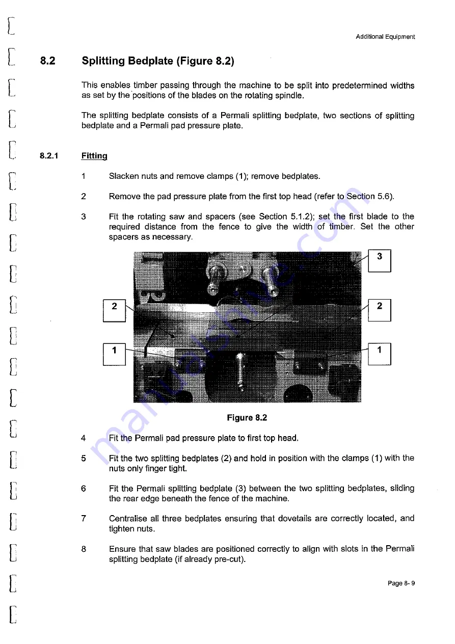
Страница 71: ...ection 5 1 2 set the first blade to the required distance from the fence to give the width of timber Set the other spacers as necessary 3 2 2 1 1 Figure 8 2 Fit the Permali pad pressure plate to first top head Fit the two splitting bedplates 2 and hold in position with the clamps 1 with the nuts only finger tight Fit the Permali splitting bedplate 3 between the two splitting bedplates sliding the ...

Страница 72: ...eath the bedplate and cut slots in the bedplate with the saws Adjust the height of the saw blades see Section 5 7 to provide the required cut to suit the timber thickness The splitting bedplate is now set up Page 8 10 w w w D a l t o n s W a d k i n c o m www DaltonsWadkin com www DaltonsWadkin com ...

Страница 73: ...ctive selection is via a two position switch located at the infeed end of the machine Additional to the switch is an air pressure regulator and air gauge When the infeed nip roller system is activated air pressure causes the top and bottom feed rolls lower raise respectively to grip the timber firmly A balance spring adjustment 3 is used to reduce unnecessary pressure on the timber when applying s...

Страница 74: ...and the equipment can be active or inactive depending upon requirements Selection is via a two position switch located at the infeed end of the machine Additional to the switch is an air pressure regulator and air gauge Side pressure rollers 3 are fitted to prevent any lateral movement of the timber as it is fed into the machine The first roller is set to contact the timber the second roller appli...

Страница 75: ... it feeds through the machine Note In this mode of operation the fence through the machine has no timber location function When setting up the fence side head see Section 5 3 with a grooved bed fitted locate the cutting edge of the cutter block approximately O 2mm in front of the fence Setting up the Cutter Block GROO EO BED PLATE C_ i ir Figure 8 5 gPlJA CIJTiER w z w g w 1 Fit the cutter block s...

Страница 76: ...king into account that the first spur cutter must align with the inside edge of the master groove and that the planing cutter tips are level with the top of the grooved bed Align the tips of the grooving cutters with the top surface of the grooved bed Page 8 15 w w w D a l t o n s W a d k i n c o m www DaltonsWadkin com www DaltonsWadkin com ...

Страница 77: ...30kW to 75kW depending upon workload requirements The unit G consists of a Permali bedplate insert through which saw cuts are made to provide support for the saw blades a splinter catching device at the infeed side of the unit a Permali pad pressure shoe and a plate carrying ten riving knives The riving knives are set in line with the saw blades so relieving stress during cutting by preventing the...

Страница 78: ...e crank handle moves the spindle away from the fence giving a positive count on the digital indicator counterclockwise rotation moves it towards the fence 8 Lock clamp 4 9 Release the pad pressure locking handle 6 and using a small crank handle supplied adjust shaft 7 to position the pad pressure slightly above that of the finished timber thickness final setting the pad pressure is carried out whe...

Страница 79: ...he finished timber width Ensure that the fingers of the splinter catching device 10 are down If necessary release locking handle 11 to lower the fingers Start the saw spindle and pass a test piece through the machine stopping when the test piece reaches the pad pressure Release the locking handle 6 and using the small crank handle adjust shaft 7 to position the pad pressure until it touches the ti...

Страница 80: ... aligned and parallel to each other ensure that all locking screws 8 are tight Continue passing the test piece through the machine to the outfeed bed Reset the side guide so that it lightly touches the timber relock with clamps 9 24 Check the test piece for quality and sawn sizes Page 8 19 w w w D a l t o n s W a d k i n c o m www DaltonsWadkin com www DaltonsWadkin com ...

Страница 81: ...achine The unit replaces the second shaft mounted feed roll at the fence side head position The unit consists of a mounting bracket 1 pneumatic cylinder 2 and mounting plate for two shaft mounted feed rolls The intermediate feed roll is set up by the beam control setting procedure o Figure 8 7 Page 8 20 w w w D a l t o n s W a d k i n c o m www DaltonsWadkin com www DaltonsWadkin com ...

Страница 82: ...height on the bed beneath the top head Reset the emergency stop Depressurise the outboard bearing by turning the pressure release screw counterclockwise Y turn using a 3mm hexagon key Lower lever 3 and hold until automatic adjustment engages If engagement does not occur rotate adjusting screw 4 to right or left until engagement is achieved Press the raisellower buttons on the machine control panel...

Страница 83: ...he cutter block 13 Lock the spindle barrel lock 2 14 15 Figure 8 8 1 III I 1 4 3 Tighten the pressure release screw and pressurise the bearing to 300bar by applying hydraulic fluid to the pressure nipple located in the recess on the front of the bearing Refit the guard Page 8 22 w w w D a l t o n s W a d k i n c o m www DaltonsWadkin com www DaltonsWadkin com ...

Страница 84: ...touching the straight edge 3 Slacken the pad pressure locking nuts 2 and position the pad pressure so that the nose is approximately 5mm from the cutter block 4 Position the pad pressure laterally over the table to suit the product width and tighten locking nuts 2 6 r 2 Figure 8 8 2 The chipbreaker comprises three individual units each is set up in the same way Set each unit as follows 5 Slacken t...

Страница 85: ...lock 10 Tighten locking nuts 5 Setting Second Bottom Head Figure 8 8 3 WARNING ENSURE THAT THE MACHINE IS ELECTRICALLY ISOLATED EMERGENCY STOP ACTIVATED BEFORE PROCEEDING Figure 8 8 3 1 Remove the guard 2 Ensure that the outfeed table is clear 3 Place a straight edge 1 on the outfeed table projecting over the cutter block The cutter blades should just touch the straight edge If necessary reset the...

Страница 86: ...e rear of the head Depressurise the outboard bearing by turning the pressure release screw counterclockwise Y i turn using a 3mm hexagon key Rotate adjusting screw 5 using the winding handle provided to position the cutter block Lock the spindle barrel lock 4 Tighten the pressure release screw and pressurise the bearing to 300bar by applying hydraulic fluid to the pressure nipple located in the re...

Страница 87: ...e position when profile jointing retract as far as possible from the cutter block using index wheel 4 Relocate head covers Second Bottom Head Jointer Figure 8 8 5 This is a built in combined straight knife and profile jointer with index wheel and traverse screw similar to the top head jointer The method of traverse and feed are similar to the top head On the second bottom head the outfeed bedplate...

Страница 88: ... straight jointing while it rotates at its operating speed normally 4500 rev min or 6000rev min This action effectively puts a flat on the edges of the blades The width of the flat Goint produced increases for every successive jointing but should exceed 0 5mm There are two types of jointing depending upon the cutter block blades to be jointed Straight across the blade is used for planing applicati...

Страница 89: ...led stone in a holder located on the machine body and secure with locking screws Position the stone relative to the cutter block using the jointer cross traverse and radial feed screws see Figure 8 8 4 Lock the jointer slide in the correct axial position ensuring that stone profile corresponds to the blades Shape the stone to the blades by turning the spindle slowly by hand termed chipping Carry o...

Страница 90: ...eaker Figure 8 9 1 The first top head pneumatic pad pressure and chipbreaker is set up as described in Section 5 6 Single acting cylinder 1 functions in the capacity of the compression spring Figure 8 9 Page 8 29 w w w D a l t o n s W a d k i n c o m www DaltonsWadkin com www DaltonsWadkin com ...

Страница 91: ... chips Cutting tool s mounted on a spindle of the machine Block of timber of known height width used as tool to datum machine settings Decibel of noise measurement of noise level Flat V or toothed belt which drives the spindles from the drive shaft Rotating rolls which move the timber through the machine while exerting necessary pressure to enable proper processing Speed at which timber is passed ...

Страница 92: ...the infeed end of the machine End of machine where finished product is produced Rotating shaft carrying the cutter block Natural movement of rotating cutter block towards away from workpiece depending upon direction of rotation Timber on which setting up processes are conducted Page 2 w w w D a l t o n s W a d k i n c o m www DaltonsWadkin com www DaltonsWadkin com ...

Страница 93: ...Vadkin CUSTOMERS ORDER ENQUIRY FORM Your Ref No Account No Telephone No Contact Name DELETE AS REQ D PLEASE ACTION AS REQUESTED Customers Signature Y j S f Date Delivery Territory Code Unit I Per Unit I Code Price Sheet No 1 of WADKIN DATAl WINSETS GENERAL MANUALSIMISClordJonn doc w w w D a l t o n s W a d k i n c o m www DaltonsWadkin com www DaltonsWadkin com ...

Отзывы: