Oil Injection (if equipped)
Rammer Repair
wc_tx000288gb.fm
92
6.2
Oil Line Check Valve
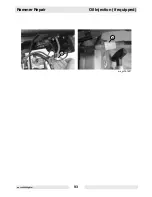
See Graphic: wc_gr001527
The the function of the oil line check valve
(a)
is to prevent raw fuel
from backing up to the oil pump. It is important that the check valve be
installed in the correct direction. Looking at the side of the check valve,
one should notice recessed areas with pointed ends or an arrow
(b)
.
The pointed ends or the arrow must point towards the fuel line. This is
the direction of oil flow.
To test the check valve:
The oil line check valve is spring operated and is designed to release
at 1.5 psi.
Note:
Initial release can be as high as 4.5 psi
.
6.2.1
Remove the oil line check valve from the oil line.
6.2.2
Attach a hand-operated vacuum pump to the outlet side (pointed end)
of the oil line check valve and operate the vacuum pump until the
vacuum overcomes the oil line check valve spring. Measure how much
vacuum it takes to operate the oil line check valve. A vacuum reading
of more than 2 psi (after initial release) is grounds for replacing the oil
line check valve.
Note:
The oil line check valve is only available by replacing the entire
hose assembly.
Newly installed oil line check valves (and those that have lost their
prime) require priming. There are two methods of priming the oil line
check valve line with oil.
Vacuum method
:
6.2.3
Attach a hand-operated vacuum pump to the fuel line end of the oil
hose.
6.2.4
Place the oil pump side of the hose in a container of 2-cycle oil.
6.2.5
Operate the vacuum pump until the oil reaches the vacuum pump.
6.2.6
Install the oil line to the oil pump and to the fuel line.
Pressure method:
6.2.7
Attach a syringe filled with 2-cycle oil to the oil pump end of the hose.
6.2.8
Inject the oil into the hose until it passes through the oil line check
valve.
6.2.9
Attach the oil line to the oil pump.
NOTICE:
The oil line check valve is an important part of the oil injection
system and should not be bypassed. Engine failure may occur.
Содержание BS 50-4
Страница 2: ......
Страница 27: ...Rammer Repair General wc_tx000284gb fm 27 Notes ...
Страница 29: ...Rammer Repair Guide Handle and Engine wc_tx000285gb fm 29 ...
Страница 41: ...Rammer Repair Guide Handle and Engine wc_tx000285gb fm 41 wc_gr001313rm a b d e c f ...
Страница 43: ...Rammer Repair Guide Handle and Engine wc_tx000285gb fm 43 e b c d wc_gr004562 a g f ...
Страница 47: ...Rammer Repair Guide Handle and Engine wc_tx000285gb fm 47 w c _ g r 0 0 1 3 1 5 r m a c b d ...
Страница 49: ...Rammer Repair Guide Handle and Engine wc_tx000285gb fm 49 wc_gr002935 d a b e c d ...
Страница 51: ...Rammer Repair Guide Handle and Engine wc_tx000285gb fm 51 d e j f wc_gr001954 b l a c k wc_gr003661 ...
Страница 53: ...Rammer Repair Guide Handle and Engine wc_tx000285gb fm 53 w c _ g r 0 0 1 3 1 7 r m a ...
Страница 55: ...Rammer Repair Guide Handle and Engine wc_tx000285gb fm 55 w c _ g r 0 0 1 3 1 8 r m b a c BS Models ...
Страница 57: ...Rammer Repair Guide Handle and Engine wc_tx000285gb fm 57 c a b wc_gr001319rm DS 720 Models ...
Страница 59: ...Rammer Repair Guide Handle and Engine wc_tx000285gb fm 59 DS 70 Models wc_gr002372rm a b c ...
Страница 61: ...Rammer Repair Guide Handle and Engine wc_tx000285gb fm 61 w c _ g r 0 0 1 3 2 0 r m H L a a b c ...
Страница 69: ...Rammer Repair Ramming System wc_tx000286gb fm 69 wc_gr001324rm Hydraulic Press Method ...
Страница 71: ...Rammer Repair Ramming System wc_tx000286gb fm 71 wc_gr001325rm Threaded Rod Method ...
Страница 81: ...Rammer Repair Ramming System wc_tx000286gb fm 81 Notes ...
Страница 84: ...Crankcase Rammer Repair wc_tx000287gb fm 84 wc_gr001333rm p o n m f ...
Страница 93: ...Rammer Repair Oil Injection if equipped wc_tx000288gb fm 93 wc_gr001527 a b ...
Страница 115: ...Rammer Repair Technical Data wc_td000112gb fm 115 NOTES ...
Страница 120: ...Technical Data Rammer Repair wc_td000112gb fm 120 ...
Страница 125: ......


