


152
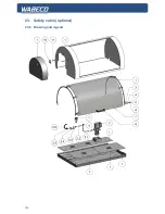
23. Safety cabin (optional)
23.1 Setting up the safety cabin
When mounting the safety cabin to a WABECO tool cabinet, the appropriate bored holes are already
present. The tool cabinet ensures a safe base for the lathe or safety cabin.
If the safety cabinet is placed and screwed to another suitable surface, the 4 through holes must be
bored into the surface by the client. For the positions of the 4 fixture threaded sockets (thread M8) of
the safety cabinet, see diagram. The diameter of the through holes in the surface must be at least 9
mm.
23.2 Mounting of the safety cabin to the tool cabinet
(optional)
■
The safety cabinet (2) is positioned, as shown, on the tool cabinet (1).
■
The screws and washers required for assembly are included in the scope of delivery.
To screw the safety cabinet to the tool cabinet
proceed as follows:
1. Combine each screw with a washer
2. Open the door or the under cabinet
3. Push the screws from below, through the bored holes in the under cabinet, into the fixture
threaded sockets and tighten using an Allen key of size 6.
Содержание D6000
Страница 76: ...76 18 Drawings and legends 18 3 Protective hood drive 2 0 kW motor...
Страница 78: ...78 18 Drawings and legends 18 4 Electronic console 2 0 kW motor...
Страница 86: ...86 18 Drawings and legends 18 10 Bed with lead screw with trapezoidal threaded spindle...
Страница 90: ...90 18 Drawings and legends 18 11 Bed with lead screw with ball screw spindle...
Страница 92: ...92 18 Drawings and legends 18 12 Change gear quadrant for trapezoidal threaded spindle and ball screw spindle...
Страница 94: ...94 18 Drawings and legends 18 13 Tool skid Transverse skid...
Страница 96: ...96 18 Drawings and legends 18 14 Tool skid Lock plate...
Страница 98: ...98 18 Drawings and legends 18 15 Tool skid Longitudinal skid...
Страница 100: ...100 18 Drawings and legends 18 16 Transverse skid with lock plate with ball screw spindle...
Страница 102: ...102 18 Drawings and legends 18 17 Tailstock...
Страница 104: ...104 18 Drawings and legends 18 18 Motor for control of the x axis...
Страница 106: ...106 18 Drawings and legends 18 19 Motor for control of the z axis...
Страница 108: ...108 18 Drawings and legends 18 20 Operating console for 1 4 kW motor...
Страница 110: ...110 18 Drawings and legends 18 20 Operating console for 1 4 kW motor...
Страница 112: ...112 18 Drawings and legends 18 21 Operating console for 2 0 kW motor...
Страница 114: ...114 18 Drawings and legends 18 21 Operating console for 2 0 kW motor...
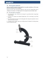
Страница 116: ...116 18 Drawings and legends 18 22 Bracket arm for operating console...
Страница 118: ...118 18 Drawings and legends 18 23 Industrial screen and membrane keyboard...
Страница 138: ...138 19 Circuit diagram 19 9 Multiphase motor with end stop...
Страница 154: ...154 23 Safety cabin optional 23 8 Drawing and legend...
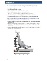
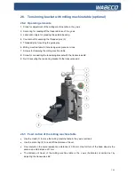
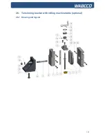
Страница 163: ...163 26 Tensioning bracket with milling machine table optional 26 7 Drawing and legend...


