background image

24

Diagnostics, Troubleshooting and Testing

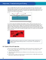
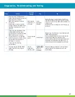
6.5  Circuit Descriptions and Diagnostics
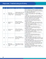
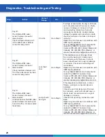
SYMPTOM CHART INDEX

Symptom Chart

Symptom Name

Symptom Chart A

OnSide BSD Radar Fails to Power Up.

Symptom Chart B

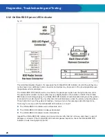
BSD LED Indicator Will Not Illuminate.

Symptom Chart C

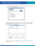
WABCO OnGuard Display Will Not Power Up.

Symptom Chart D

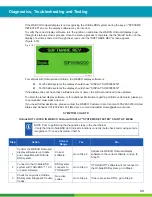
OnSide Not Listed in WABCO OnGuard Display "SYSTEMS DETECTED" Start-Up 
Menu.

Symptom Chart E

No WABCO OnGuard Display Blind Spot Zone Moving Vehicle Recognition with 
Right Turn Signal Activation (Relay System).
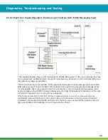
Symptom Chart F

No WABCO OnGuard Display Blind Spot Zone Moving Vehicle Recognition with 
Right Turn Signal Activation (J1939 CAN System).

Symptom Chart G

OnSide BSD System Does Not Recognize Moving Vehicles Correctly.

6.5.1  OnSide BSD Radar Sensor

Fig. 6.12 

4016860b

Содержание OnSide MM16167

Страница 1: ...MM16167 OnSide BLIND SPOT DETECTION SYSTEM MAINTENANCE MANUAL...

Страница 2: ......

Страница 3: ...to Obtain Replacement Components 6 3 1 If Tools and Supplies are Specified in This Manual 7 4 OnSide Warnings Cautions and Operating Guidelines 7 4 1 Driver Related Information 7 4 2 Environment Rela...

Страница 4: ...ng is ignored NOTICE Description of a possible situation which may result in material damage if the warning is ignored Important information notes and or tips Reference to information on the internet...

Страница 5: ...wabco academy com home WABCO online product catalog https www wabco customercenter com Your direct contact to WABCO WABCO North America LLC WABCO USA LLC 1220 Pacific Drive Auburn Hills MI 48326 Custo...

Страница 6: ...ury damage to components or both WARNING To prevent serious eye injury always wear safe eye protection when you perform vehicle maintenance or service WARNING Park the vehicle on a level surface Block...

Страница 7: ...e property damage The driver is responsible for understanding the operation and limitations of the OnSide BSD system before operating the vehicle Failure to do so can result in serious personal injury...

Страница 8: ...ior to driving Wait until the vehicle is parked to retrieve items that have fallen to the floor Driving while distracted can result in serious personal injury or death and or severe property damage WA...

Страница 9: ...change procedures Alerted by an OnSide warning the driver must take corrective measures to avoid an imminent side collision Drivers must remain aware of their surroundings by looking and using all ava...

Страница 10: ...ipment carried out at a qualified specialist workshop If there is a malfunction and the system cannot provide assistance the LED indicator mounted on the A pillar may not illuminate at all may continu...

Страница 11: ...urn signal activation OnSide was designed to be a standalone system no other WABCO systems are required to be installed on the vehicle for OnSide to function OnSide is compatible with other WABCO syst...

Страница 12: ...cle s passenger side blind spot zone The radar continuously detects a wide variety of stationary and moving objects in the vehicle s passenger side blind spot while the algorithm filters out the stati...

Страница 13: ...or Fig 5 4 4016837a Fig 5 5 No Vehicle Detected Vehicle Detected Fig 5 5 The OnSide BSD system constantly monitors the vehicle s passenger side blind spot zone for moving vehicles When the system dete...

Страница 14: ...MS DETECTED start up menu Figure 5 7 Fig 5 7 4016841a The WABCO OnGuard display also provides additional visual Figure 5 8 and audible warnings The additional audible and visual warnings from the disp...

Страница 15: ...hicle OEM Your installation may use a spacer of some type Some spacers have a Wedge shape Figure 5 11 others may use an Adapter Shim Housing Figure 5 12 with a number of Shims Figure 5 13 The examples...

Страница 16: ...use the WABCO OnSide BSD harness Figure 5 14 it will have the BSD radar sensor connector and BSD LED indicator connector and the turn signal input relay will be tapped to the harness The harness will...

Страница 17: ...al Checks When the ignition is turned on the OnSide BSD LED indicator will illuminate briefly for a bulb check Figure 6 1 and then go out Figure 6 2 indicating the system is ready for use Fig 6 1 4016...

Страница 18: ...d a visual Blind Spot Alert Figure 6 6 warning message shown on the display The chirps and Blind Spot Alert warning message will continue as long as the vehicle is traveling above 15 mph 24 2 km h the...

Страница 19: ...the correct software 6 3 TOOLBOX Software WABCO TOOLBOX Software version 12 9 or later is the only software that can be used to fully communicate with and diagnose the OnSide BSD system To obtain TOOL...

Страница 20: ...016857a When the Diagnostic Trouble Code DTC screen opens all of the DTCs active and stored should populate The list will provide the DTC Status number of Occurrences the SPN the FMI and the SYSTEM St...

Страница 21: ...c Trouble Code table contact the WABCO Customer Care Center at 855 228 3203 for assistance OnSide BSD SYSTEM DIAGNOSTIC TROUBLE CODES SPN FMI DTC Description DTC Detection Method Action 894 3 BSD sens...

Страница 22: ...cator lamp pigtail for damage or short to voltage 894 6 LED Short to Ground LED is continuously monitored to check for a short to ground Verify the LED indicator lamp wiring circuit connectors are not...

Страница 23: ...auto com for technical service questions 894 11 BSD sensor software fault Internal software fault in the side sensor that a ects the sensor performance Inspect the BSD radar sensor for any signs of da...

Страница 24: ...r Up Symptom Chart D OnSide Not Listed in WABCO OnGuard Display SYSTEMS DETECTED Start Up Menu Symptom Chart E No WABCO OnGuard Display Blind Spot Zone Moving Vehicle Recognition with Right Turn Signa...

Страница 25: ...perform an ignition on Bulb check but will indicate moving vehicles in blind spot zone when traveling above 15 mph 24 2 km h The OnSide BSD LED indicator works intermittently Inspect the OnSide BSD r...

Страница 26: ...nce is out of range check the circuit between pin 10 and ground for continuity verify there are no shorts loose connections and no sign of damage or corrosion Check all circuit wiring and connections...

Страница 27: ...between the OnSide BSD LED harness connector pin 1 and the OnSide BSD radar sensor harness connector pin 4 for continuity verify there are no shorts loose connections and no sign of damage or corrosi...

Страница 28: ...nctioning properly the OnSide BSD LED indicator should illuminate briefly when the ignition is turned on for a bulb check The only other time it should illuminate is when the vehicle is traveling abov...

Страница 29: ...ED harness connector pin 2 and ground for continuity verify there are no shorts loose connections and no sign of damage or corrosion Repair any circuit issues in accordance with OEM repair guidelines...

Страница 30: ...ly The exact location of the WABCO OnGuard display on the dash or under behind the dash may vary slightly based on the installer or OEM For either configuration the display circuit is the same If the...

Страница 31: ...OTE Prior to performing the diagnostic steps in the chart below If the WABCO OnGuard display screen is dark verify that the display screen brightness settings are not all the way down Verify that the...

Страница 32: ...bright Go to Step 4 If the lamp does not illuminate is dim or flickers a wiring or connection issue is indicated Check the pin 4 circuit and pin 5 circuit for continuity verify both circuits have no s...

Страница 33: ...de or OnGuard please go to our website www wabco na com If you need further assistance please contact the WABCO Customer Care Center at 855 228 3203 United States and Canada 001 800 889 1834 Mexico or...

Страница 34: ...d Display and harness for signs of damage or corrosion Visual inspection checks good WABCO OnGuard Display failure is indicated Physical damage indicates unit has failed and will need to be replaced a...

Страница 35: ...resents the right turn signal relay circuit Although they may not be shown here additional in line connectors and splices may be present in the circuit depending upon the particular vehicle and instal...

Страница 36: ...Step 2 If resistance is out of range go to Step 3 2 Key on Right turn signal on OnSide BSD radar sensor harness connector disconnected Check resistance between BSD radar sensor harness connector pin...

Страница 37: ...t pin 1 86 and the vehicle ground circuit for continuity verify there are no shorts loose connections and no sign of damage or corrosion Check all circuit wiring connections May need to see OEM refere...

Страница 38: ...n signal on Turn signal input relay disconnected from the relay socket Load test across socket pins 1 86 and 2 85 with a 2 4 amp sealed head lamp Lamp should continuously alternate between on bright a...

Страница 39: ...will monitor the SAE J1939 network for the right turn signal activation message When the OnSide BSD radar sensor sees the right turn signal active in the turn signal switch parameter it will send a m...

Страница 40: ...4 Check for any active vehicle J1939 DTCs No active vehicle codes Go to Step 5 If other vehicle system J1939 DTCs are found they should be corrected prior to diagnosing the OnSide BSD system Go to St...

Страница 41: ...orrectly and are compatible with OnGuard and OnSide in accordance with OEM guidelines Settings software and hardware correct Go to Step 7 Update software parameters settings and or hardware that were...

Страница 42: ...m Chart B 2 Confirm that OnSide is shown in the WABCO OnGuard Display Start up SYSTEMS DETECTED screen if equipped OnSide recognized Go to Step 3 Go to Symptom Chart D 3 Verify the OnSide BSD system f...

Страница 43: ...f the system detects vehicles outside of the blind spot zone verify that the BSD radar sensor is mounted correctly The angles and measurements below apply to both Fairing and Step mounted OnSide BSD s...

Страница 44: ...or fascia assembly to the vehicle 4 While holding the BSD radar sensor in place disconnect the harness connector from the radar sensor 5 Remove the radar sensor bracket assembly shim housing and shims...

Страница 45: ...ounted Radar Sensor Assembly Replacement 7 1 2 1 Assembly with Bracket P N 400 874 014 4 Fig 7 2 4016874b Removal With Bracket P N 400 874 014 4 1 Turn the ignition switch to the OFF position 2 Place...

Страница 46: ...step 2 Install the radar sensor over the studs into position on the radar mounting plate 3 Install the M8 flanged lock nut and two M6 flanged lock nuts tighten the M8 flanged lock nut to 61 75 in lb 6...

Страница 47: ...and remove it from the A pillar trim panel CAUTION Make sure not to damage the OnSide BSD LED indicator or the A pillar trim panel during removal 3 Carefully pull the OnSide BSD LED indicator pig tail...

Страница 48: ...ructions for correct procedures 3 Disconnect the display harness connector from the display Figure 7 6 4 Remove the two 6 32 nuts and save for installation of the new display 5 Remove the display from...

Страница 49: ...e ignition switch to the OFF position 2 Place blocks under the rear tires to prevent the vehicle from moving Apply the parking brake 3 Locate where the turn signal input relay is taped to the WABCO On...

Страница 50: ...50 Component Replacement Procedures...

Страница 51: ...51 Component Replacement Procedures...

Страница 52: ...comprehensive solutions for established vehicle manufacturers and newly emerging transport and mobility service providers ZF electrifies different kinds of vehicles With its products the company cont...

Отзывы: