


Vtronix
3
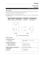
With the cover removed, connect the wires from the heating/cooling equipment to the terminals on the
thermostat base. See wiring diagram (Fig. 5) for location of thermostat terminals.
Put the front cover back to the thermostat by having
POWER
&
FAN
switches locked by the caps and then
slide to the left.
Secure the front plate by using the locking screw.
Insert the temp. knob to the thermostat, make sure it
is put with the same alignment & position as shown.
OPERATION
Set-up Switch
The set-up switch is an internal switch (E, F) that is
located on the thermostat base. See Fig. 9. It is used
to select the type of heating system being used.
The E position is for electric heat applications.
The F position is for gas or oil heat applications.
WARNING
Fire Hazard.
Failure to set the set-up switch to the E position
when electric resistance heat is used may result in
the overheating of the electric heater elements due
to improper fan operation
Fig. 5. Connect system wires to thermostat terminals (strip 5/16 IN).
Fig. 6. Put front cover back & Slide switches to the left.
Fig. 7. Secure the front plate.
Fig. 9. Location of set-up switch on thermostat base.
Set-up switch
Fig. 8. Verify thermostat shaft is properly aligned.